CT-600-2 41
10 ACP LINK, user guide
Normal operation of the ACP is done through the HMI on the ACP LINK panel.
Operation of the electrical panel IO-module is only necessary during commissioning of the system, where the
module will be configured or when any changes are made to the configuration of that module. See the section
in the end of this chapter for further information.
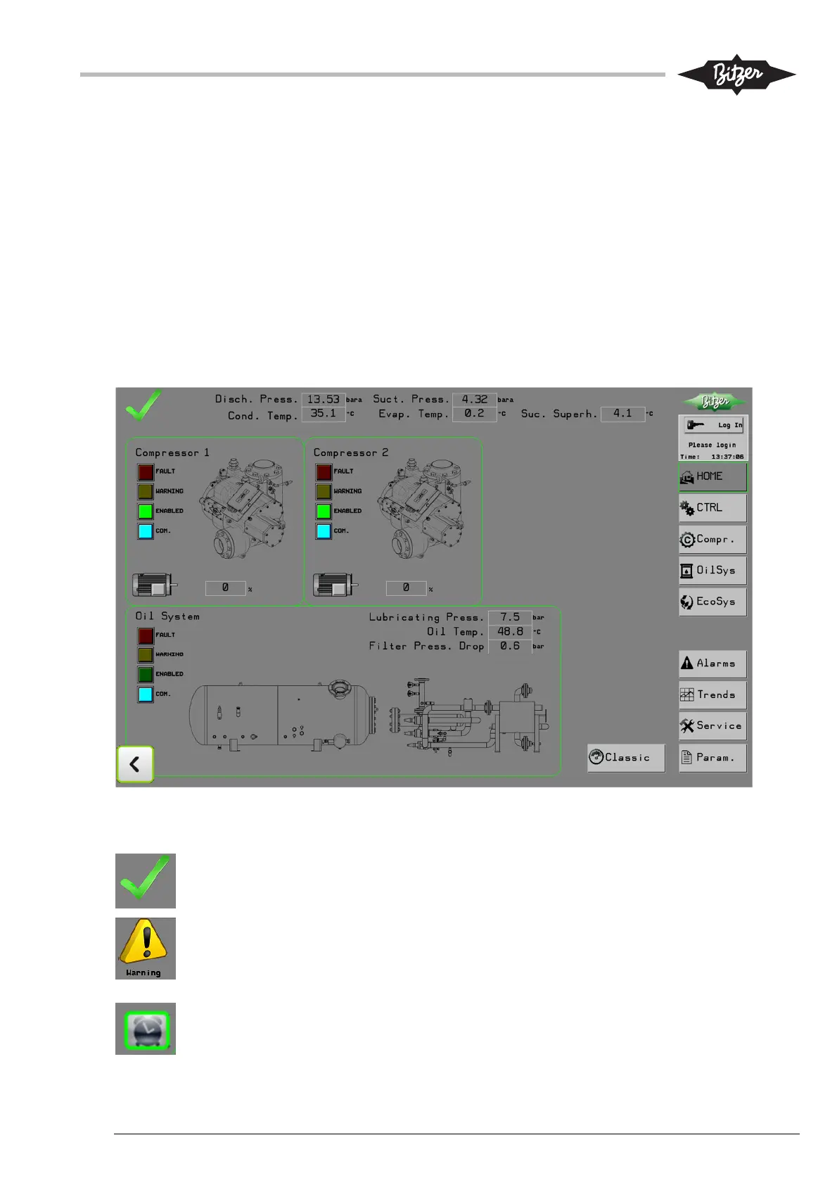
10.1 Home screen (Home)
Operating the ACP starts normally from the Home screen on the ACP LINK HMI, which gives an overview of
key parameters and operation status. Access to other HMI screens can be found on the right side on all
screens, with buttons that link to the other screens. The top right corner shows the actual user level and a
button to log in or out. On the Home screen, hot spots around the pictures for compressor and oil system act
as links to the screens for those components.
In the top left corner is an indication for the current status of the ACP.
The green symbol indicates that all is okay and everything is running normally.
The yellow exclamation mark indicates an alarm is present. The symbol is a link to the Alarm
screen, where all active alarms are shown. The text indication “Warning” means that a warning
is present. The symbol is a link that will link to the warning page, where all the active warnings
are shown.
The clock symbol indicates a timer is active. The symbol is a link to the timer page on the
Parameter screen. On the timer page, the user can browse through the pages until the active
timer is located (indicated by a green lamp next to the timer).