36 CT-600-2
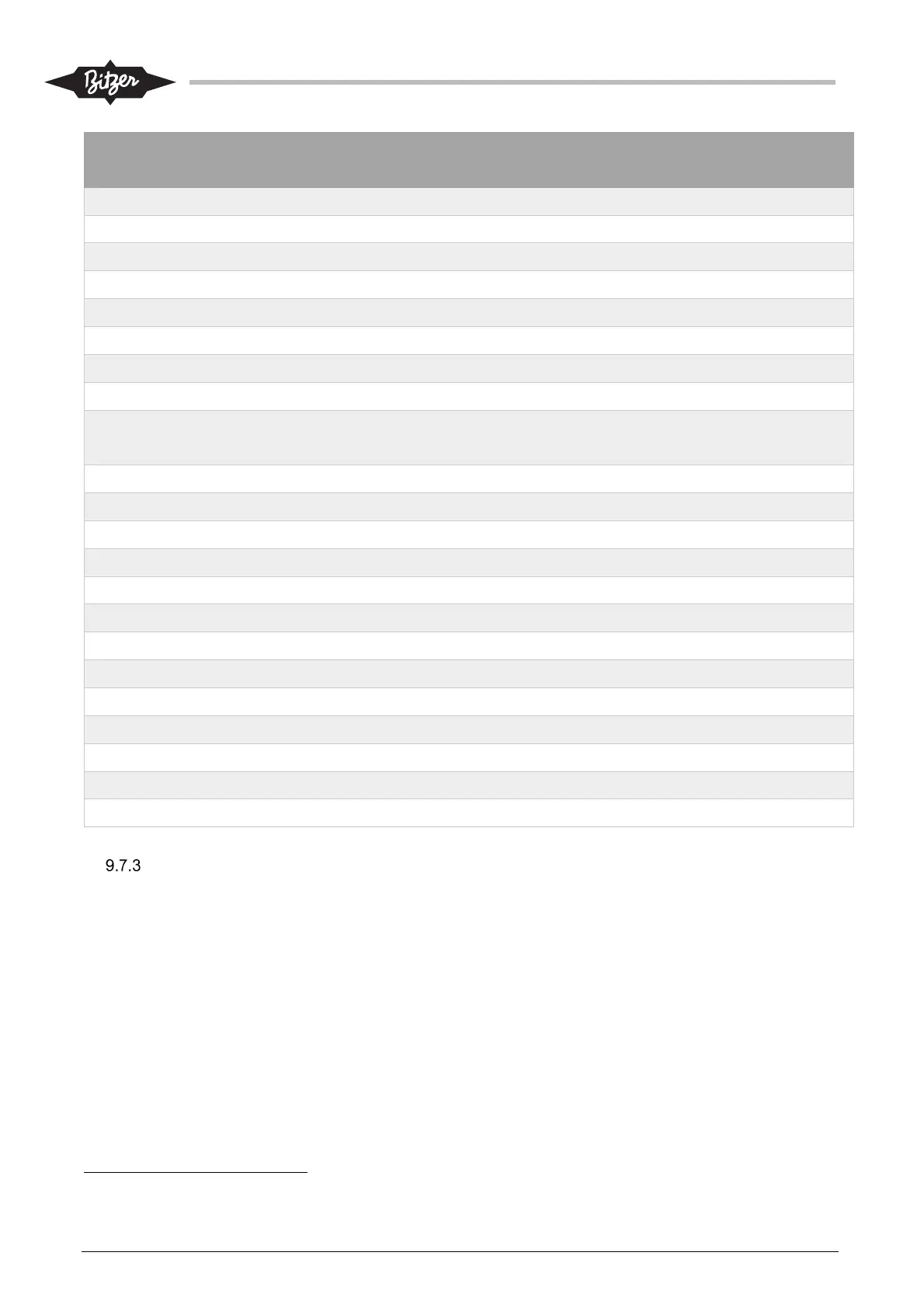
Parameter WEG Par.
No.
Value Note
LOC/REM Selection Src 220 1: Always REM
LOC JOG Selection 225 0: Disable
REM JOG Selection 228 0: Disable
Stop mode selection 229 1: Coast to Stop
Dead Zone (AIs) 230 1: On
AI1 Signal Function 231 0: Speed Ref.
AI1 Signal Type 233 0: 0 – 10V
AO1 Function 251 5: Output Current
AO1 Signal Type 253 0: 0 – 10V /
4-20mA
Optional “1: 4 – 20mA”, requires adjustment
of VSD dip-switches, acc. to WEG manual
DI1 Function 263 1: Run/Stop
DI2 Function 264 0: Not Used
DI5 Function 267 0: Not Used
DI6 Function 268 0: Not Used
DO1 Function (RL 1) 275 11: Run Feedback for CM-SW-01 Comp. module
DO2 Function (RL 2) 276 26: Fault Alternative: “13: No Fault” (not fail-safe!)
Application 298 1: Heavy Duty
Fan Control Config: 352 4: HS-CT, Int-ON
Motor Rated Voltage 400 Motor specific Acc. motor nameplate/datasheet – See note
5
Nominal Current 401 Motor specific Acc. motor nameplate/datasheet – See note
2
Nominal Rated Speed 402 Motor specific Acc. motor nameplate/datasheet – See note
5
Motor Rated Frequency 403 Motor specific Acc. motor nameplate/datasheet – See note
5
Motor Rated Power 404 Motor specific Acc. motor nameplate/datasheet – See note
5
Speed set point settings in ACP LINK
The speed set point is send to the variable speed drive as an analog 0-10 V signal, coming from the electrical
panel IO-module. The speed set point in the ACP LINK PLC (output from M251 PLC to M172) is calculated in
the range 0 – 1000, which corresponds to 0 – 10V output from the M172 electrical panel IO-module. The
calibration of output is done on the ACP LINK HMI and must correspond to the calibration of the analog input
on the variable speed drive (see also section 9.2).
The formula used to calculate the output signal, based on the set point for the frequency is:
Output [0..1000] = frequency_setpoint [Hz] * A + B. Output “1000” equals 10V.
Standard recommended parameters are shown in table below:
2
NOTICE: WEG 300V-70Hz motors: adjust to values for 70Hz / 400V! – Do not use data for 300V!