18 CT-600-2
Terminal plan ACP LINK panel
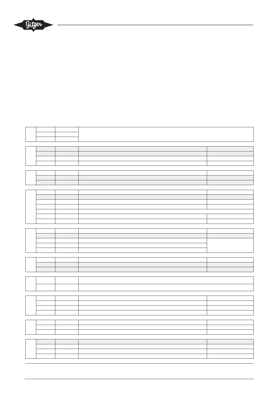
7.2 Electrical panel IO-module (M172)
The M172 module for the electrical panel is supplied loose and to be installed by the customer (see also
section 6.3). The terminal plan below shows how to connect the module to the ACP LINK panel, the plant,
the optional eco system module and optional sensors. Section 11.1 gives an overview of the I/O signals and
further descriptions. For BITZER supplied electrical panels, the M172 module is installed and partly pre-
wired.
Terminal plan electrical panel I/O module (M172)
CN19
GND RS485‐1GS
FromACPHMI.Installedandcablesuppliedbycustomer(3x0,6ModbusRTUstandard,Belden3106Aor
equivalent).Terminatewith120Ωresistor
‐ RS485‐1‐
+ RS485‐1+
CN15
DO11 Notused(spare) Upto250V,3A
DO10 Notused(spare) Upto250V,3A
DO9 Ecosystemrunning Upto250V,3A
C91011 Common
CN14
C12 Common
DO12‐ Notused(spare) Upto250V,1A
DO12 Notused(spare) Upto250V,1A
CN13
AI9 + Processtemperature PT1000default
AI10 + Auxilarytemperature(notused) PT1000default
AI11 + Remotesetpoint1 0‐10Vdefault
AI12 + Remotesetpoint3/ExternalCapacityLimiterinAutomode 0‐10Vdefault
GND Connecttoallvoltagesensorsand3‐wirecurrentsensors
5Vdc Usefor0‐5Vrat.(whereapplies)
24Vdc Useforcurrentsensors
CN12
COM‐DI 24VDC‐
DI9 Notused(spare)
DI10 24VDC+ Drive/motorerror1
Contactinmotorordrive
DI11 24VDC+ Drive/motorerror2
DI12 24VDC+ Drive/motorerror3
CN11
GND Common
AO5 + Notused(spare)
AO6 + Notused(spare)
CN10
‐ 24VDC‐ Customersupplyfromtransformerinelectricalpanel,typeTfuse2A
+ 24VDC+ Customersupplyfromtransformerinelectricalpanel,typeTfuse2A
CN9
C2 Relay CommonforD02
DO2 Relay Commonalarm Upto250V,3A
C1 Relay CommonforD01
D01 Relay Shutdown Upto250V,3A
CN8
DO4 Relay Runsignal Upto250V,3A
DO3 Relay Readyforoperation Upto250V,3A
C34 Relay Common
CN7
DO7 Relay Notused(spare) Upto250V,3A
DO6 Relay Startrequestchillerpump Upto250V,3A
DO5 Relay StartpermissionHP/LP(forboosteronly) Upto250V,3A
C567 Relay Common