You can adjust settings such as iris, focus and zoom in the same way you would an
active MFT lens, either via an ATEM switcher using the ‘camera control’ page, or via
other remote control interfaces that can be connected to the Micro Studio Camera 4K
expansion cable. For a list of supported B4 digital lenses, refer to the Blackmagic
Design support center at www.blackmagicdesign.com/support/faq/59011
6 S.Bus Digital Servo
By connecting to a compatible S.Bus receiver using the Futaba J cable, you have
17S.Bus remote channels where features of the camera can be assigned to and
remotely controlled. Channel 18 is reserved as a reset switch so that the camera can be
reset to its default exposure settings. These features can include focus, servo zoom, iris
control and other such features. For more information about mapping functions to S.Bus
remote channels, see the ‘Remote Settings’ section of this manual.
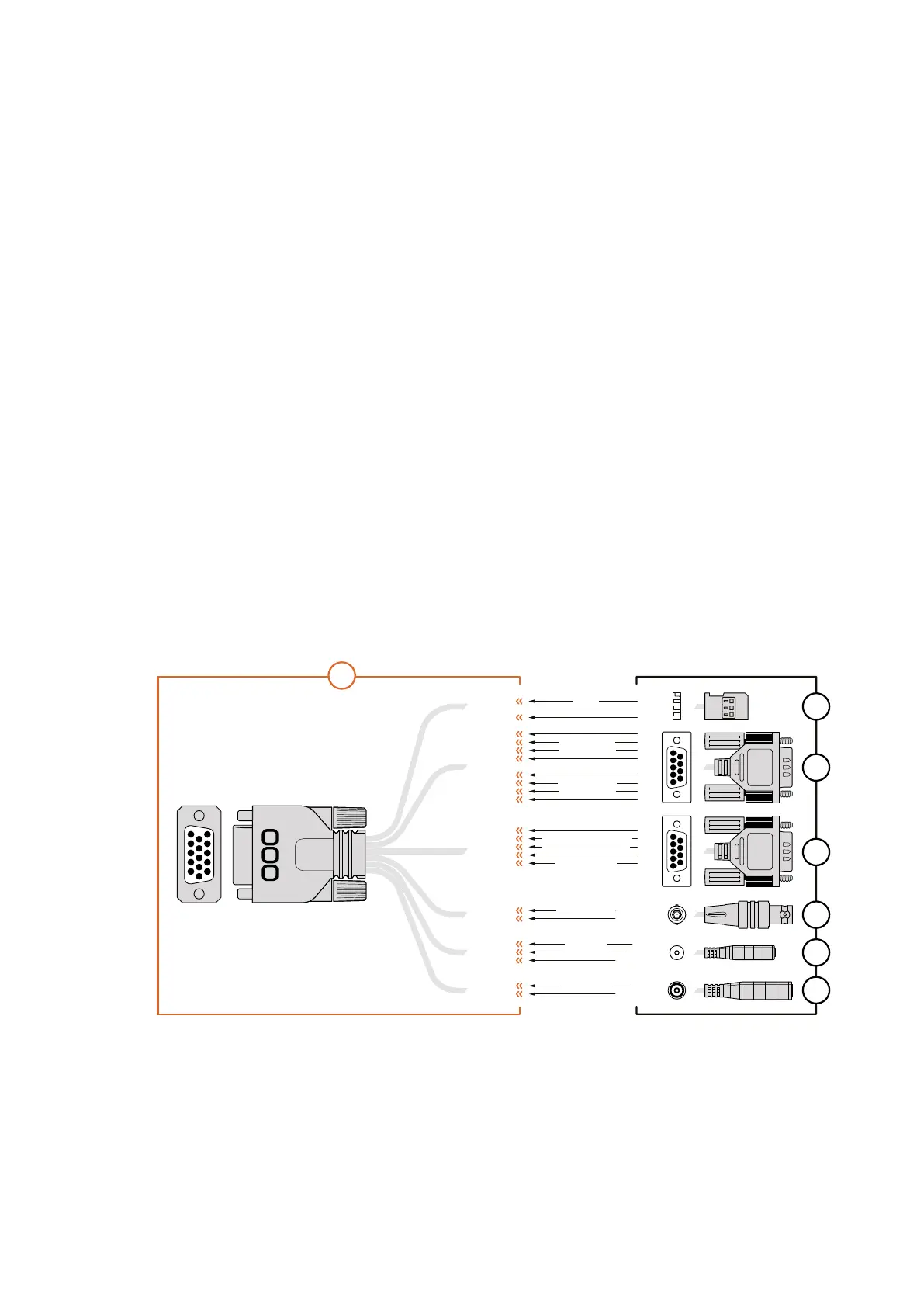
Wiring diagram for the Blackmagic
MicroStudio Camera 4K Expansion Cable
When using Blackmagic Micro Studio Camera 4K’s expansion port you may only want to access
one or two functions. For example, you may want to control an attached B4 Broadcast Lens
while simultaneously receiving 12V power and a reference signal. It’s easy to make a connector
that will give you just these functions without the clutter of additional, unused connectors.
Use the following diagram when wiring the expansion cable included or use it as an example for
how you can wire up the connections on your own custom cable correctly. The full range of
available pins are listed under group P1, while the subsets used for particular functions, as well as
their layout within the appropriate connectors, are shown in groups P2 through P7.
PIN ASSIGNMENT
1
2
3
1
2
3
4
5
6
7
8
9
1
2
3
4
5
OTHER
CENTER
SLEEVE
PIN
SLEEVE
2
GROUND
GROUND
12
8
GROUND
GROUND
13
3
GROUND
GROUND
14
15
GROUND
6
5
GROUND
6
GROUND
9
10
GROUND
TIP
RING
SLEEVE
1
2
3
4
5
6
7
8
9
1
2
3
4
5
6
7
8
9
P2
P3
P4
P5
P6
P7
P1
1 Ground
2 S. Bus
3 PTZ RS422 Tx-
4 Ground
5 Reference Input
* Power input to the camera is also used to power the lens. Beware of applying excessive voltages if you’re using
your own power supply to avoid damage to the lens.
6 Power +12V in
7 Ground
8 PTZ RS422 Tx+
9 LANC Data
10 LANC Power
11 Ground
12 PTZ RS422 Rx-
13 PTZ RS422 Rx+
14 B4 Lens Control Transmit
15 B4 Lens Control Receive
S. Bus
PTZ RS422 Rx-
PTZ RS422 Tx+
PTZ RS422 Rx+
PTZ RS422 Tx-
B4 Lens Control Transmit
B4 Lens Control Receive
Power +12V in*
Reference Input
LANC Data
LANC Power
Power +12V in
1
2
3
4
5
11
12
13
14
15
6
7
8
9
10
1818Customization

 Loading...