Group 03, Section 01, Page 6 Mechanical Dock Leveler – M and FMC
Issue Date: 10/01/01, Rev, 0 (Part #038-550E)
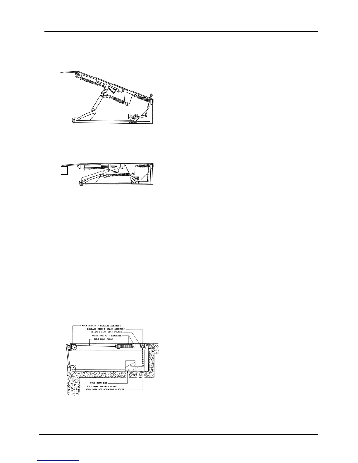
DETAIL OF COMPONENT FUNCTIONS – cont’d
In this view the deck has been allowed to
raise to the point where the actuator
extended the lip. Notice that as the
actuator assembly moved forward – the lip
lock was pulled into its locking position.
The spring will maintain tension on the lip
lock while the deck is in the raised
position. When the deck is walked down
by the weight of the operator – the weight
of the lip will be supported by the lip lock.
After the loading / unloading process is complete – the operator pulls the release
chain to release the hold down device. The operator can now allow the dock deck to
raise high enough to allow the lip (now unlocked) to drop into its hanging position.
The lip is now ready and in position to enter the lip keepers when the operator walks
it down.
The lip and the lip keepers will now support the outer weight of the deck assembly in
the stored position.
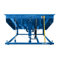
We have previously referred to the
opposing force or braking action of the
hold down box and cable, on the biased lift
springs. In this picture we can follow the
cable routing. The cable is attached
through a float spring to the rear solid
portion of the dock leveler deck. It is
routed forward to a pulley that is mounted
at the front of the deck. It then proceeds
downward through another pulley that is
mounted on the lower front beam of the
stationary frame. The cable then extends
rearward where it enters the hold down
box where tension is applied by a rewind
spring.
This view shows the deck lowered and the
weight of the deck now being supported by
the truck floor.
At this time the actuator and the lip lock
have done their job. Because the weight of
the lip has been taken by the truck floor –
the weight of the lip is no longer exerting
force on the lip lock. The fact that the Lift
Arm is now in a lower position – the spring
is relaxed – gravity takes over and allows
the lip lock to drop out of locked position.