Group 06, Section 02, Page 2 Mechanical Dock Leveler – M and FMC
Issue Date: 10/01/01, Rev, 0 (Part #038-550E)
ADJUSTMENT SEQUENCE and INSTRUCTIONS – cont’d
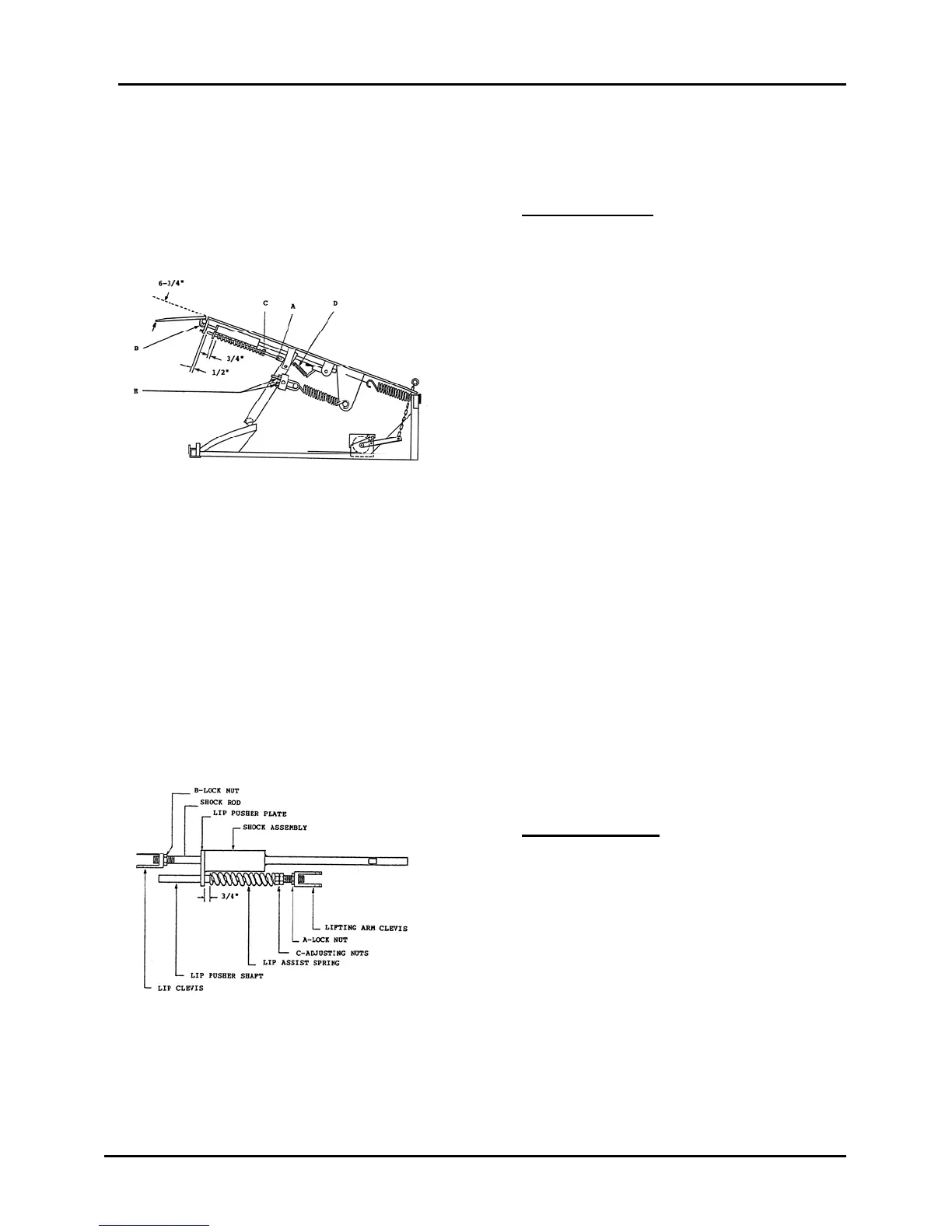
Step Number 2: Place a straight
edge on the top surface of the deck,
extending out over the lip area an
amount equal to the length of the lip.
Measure the distance from the
underside of the straight edge to the
underside of the tip of the lip, 6-1/2”
to 7” is the correct measurement,
required, see Figure 2. To adjust,
loosen the shock rod locknut ‘B’,
Figures 2 and 3, and turn the shock
rod into or out of the lip clevis to
achieve the correct measurement.
Relieving the weight of the lip from
the clevis and rod will reduce the
effort required to turn the shock rod.
Hold the shock rod and tighten the
locknut against the clevis when
setting is correct.
Figure 2
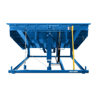
Figure 3 is a bottom view of the lip
extension components.
A – Lock Nut Lip Pusher Shaft.
B – Lock Nut Lip Shock Rod.
C – Adjusting Nuts Lip Assist Spring
Step Number 3: Position the lip assist
spring against the spring adjustment
nuts ‘C’, Figure 3. Measure the
distance between the lip pusher plate
and the end of the spring, 3/4” is the
correct space required. To adjust, hold
the nut that makes contact with the
spring and loosen the other nut. Turn
both nuts toward or away from the
spring to achieve the correct
measurement. Hold the nut that makes
contact with the spring and tighten the
other nut against it when the setting is
correct.
Figure 3