Group 08, Section 11, Page 2 Mechanical Dock Leveler – M and FMC
Issue Date: 10/01/01, Rev, 0 (Part #038-550E)
REPLACEMENT PROCEDURES - cont’d
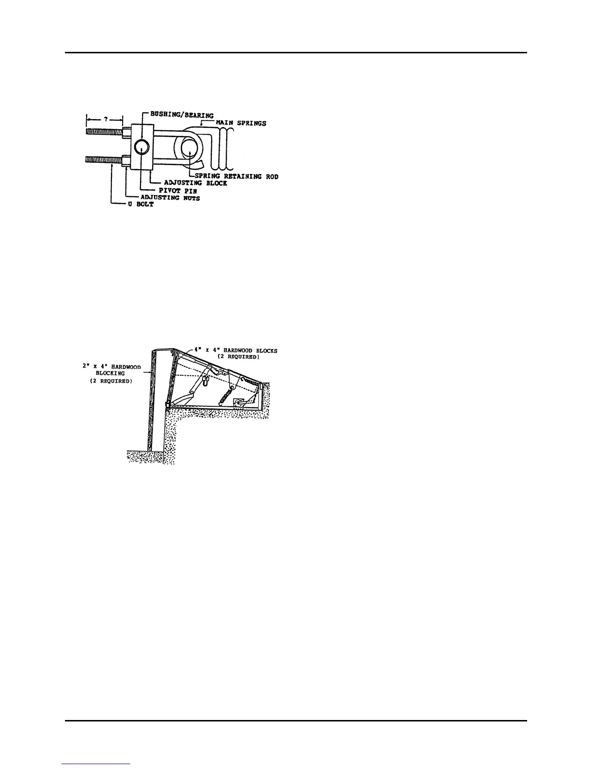
3) Measure and record the length of 'U'
bolt thread showing between end of 'U'
bolt and face of adjusting nuts, Figure
50. This will be used as an initial
adjustment on reassembly
Figure 50
4) Turn off the 'U' bolt adjusting nuts, Figure 50 counterclockwise. Maintain
approximately the same tension on each nut by making four full turns on each nut
and repeating. Check blocking as the weight is transferred onto them to assure
they remain in a position that will insure the deck will not lower.
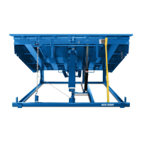
5) Measure the distance from the
underside of the tip of the lip to the
driveway surface. Cut 2 sound pieces
of 2" x 4" hardwood blocks 1" longer
than the dimension measured. Eg: If
distance measured was 60" long, cut
the blocks 61" long.
Figure 51
6) Lift the tip of the lip up and position the blocks vertically between the driveway and
the underside of the tip of the lip, to create a positive means of maintaining the lip in
its horizontal position. See Figure 51.
7) Proceed with repairs or replacement of faulty componetns as required, and upon
completion, replace lifting springs, ‘U’ bolts and adjusting nuts, in reverse order or
removal.
8) Apply tension to the main springs by turning the 'U' bolt adjusting nuts clockwise.
Maintain equal tension on each adjusting nut by making four full turns on each of
the four nuts and then repeating. Continue until all four nuts are located to produce
the dimension noted in Step 3. See Figure 50. This is an initial adjustment only.