Mechanical Dock Leveler – M and FMC Group 08, Section 17, Page 7
Issue Date: 10/01/01, Rev. 0 (Part #038-550E)
LONGER LIP REQUIREMENT – cont’d
Move Dock Leveler Forward
Finish weld the ends of the filler beam to
the side curb angles, 1/4" x 4" long weld,
both ends.
Finish weld all shims and spacer shims.
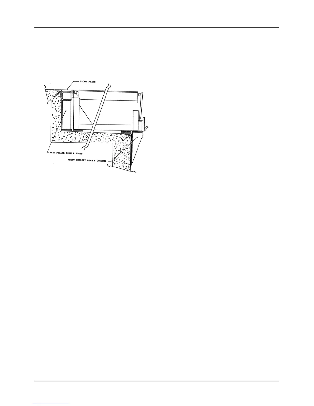
Fit and place the floor plate into the
space between the rear curb angle and
the dock leveler back beam. Assure the
top surface is flush with the top surface
of both the curb angle and back beam.
Tack-weld in six places minimum,
Figure 104..
Finish weld the floor plate to the
surrounding components, curb angle,
back beam and side curb angles.
1/4" x 6" long welds on 12" centers.
Full length 1/4" welds both ends.
Position the 4” long dock bumper
extensions, tack-weld to maintain
position, and finish weld as securely as
possible. Use lag bolts in addition to
welding, if required by the application
conditions.
Remount the dock bumpers securely to
the bumper extensions.
Clean-up entire work area and paint all
weld and burn areas as required.
Remove safety stand, lower
maintenance strut and lower dock leveler
to stored position. Test operate the dock
leveler to assure adjustments are
correct.
Figure 104