Group 08, Section 17, Page 6 Mechanical Dock Leveler – M and FMC
Issue Date: 10/01/01, Rev, 0 (Part #038-550E)
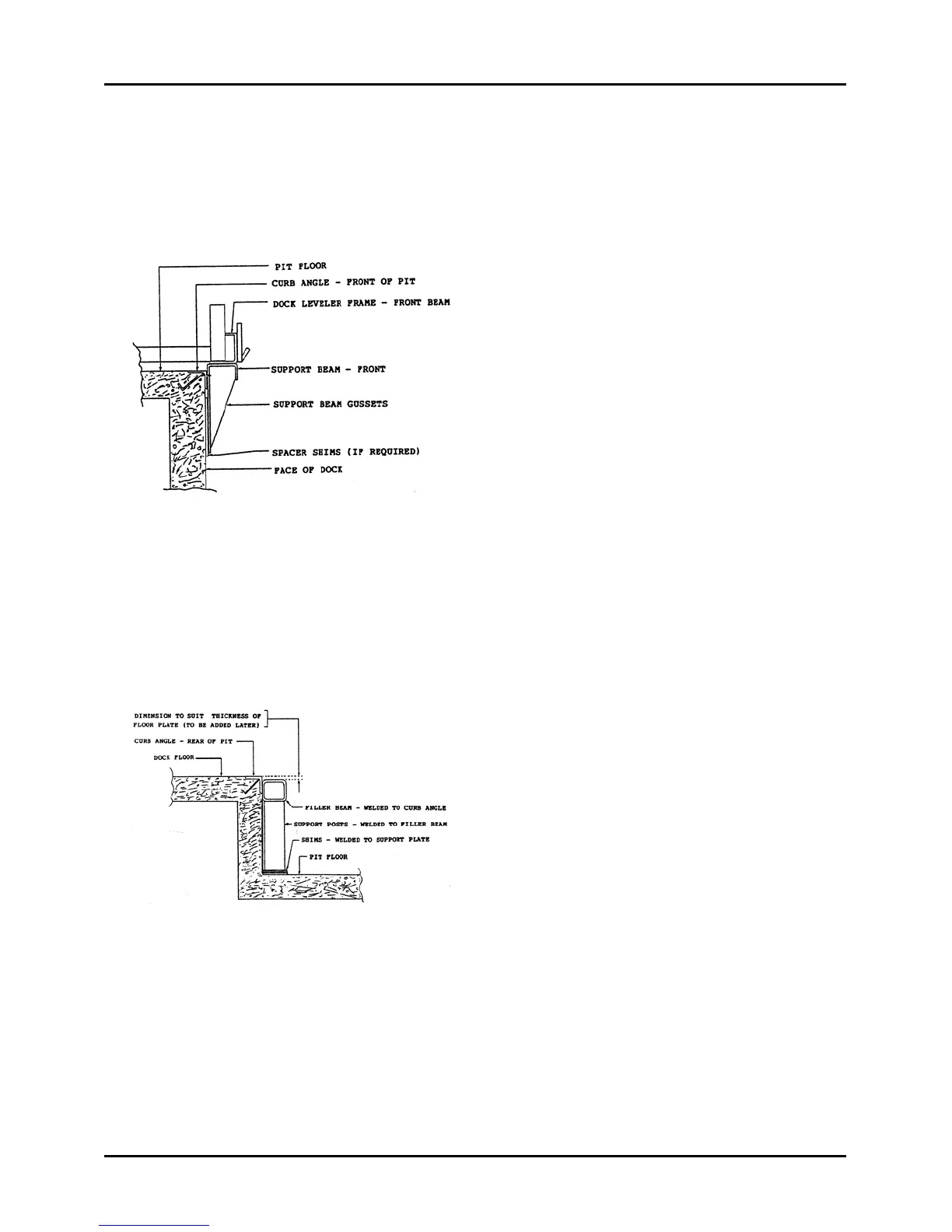
LONGER LIP REQUIREMENT – cont’d
Move Dock Leveler Forward
Figure 102 is a side view of the front
beam of the dock leveler extended out of
the pit and supported with a full width
front support beam that is welded to the
front pit curb angle and the dock leveler
front beam. Note: The vertical back
plate of the support beam must be in
positive contact with the face of the dock.
Weld spacer shims into place as shown
and as required.
Position the front support beam into
place against the underside of the dock
leveler front beam, centered, and in
against the front pit curb angle. Block in
this position and tack-weld to the curb
angle and front beam. Remove the
positioning blocks and inspect the
location of the vertical back plate of the
support beam in relation to the face of
the dock. If the vertical plate is not in
positive contact with the dock face, install
and tack-weld suitable spacer shims
behind each support beam gusset to fill
the space between the vertical plate and
the dock face.
Finish weld the front support beam to the
front curb angle. 3/8" x 6" long welds on
12" centers.
Finish weld the front support beam to the
dock leveler front beam. 3/8" x 6" long
welds on 18" centers, face of beams.
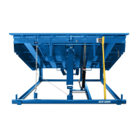
Finish weld the rear filler beam to the
rear curb angle. 1/4" x 8" long welds on
each end and 1/4" x 6" long welds on
9-5/8" centers across full width, Figure
103.
Finish weld the rear filler beam to the
dock leveler back beam 1/4' x 8" long
welds on each end and 1/4" x 6" long
welds on 9-5/8" centers across full width.
Figure 102
Figure 103