Probus DP V1 Agile 4506/2010
0
Ready to Switch On
1
Switched On
2
Operation enabled
3
Error
4
Voltage enabled
5
Quick Stop
6
Switch On disabled
7
Warning
8
no function
9
Remote
10
Reference value reached
11
Limit value reached
12
no function
13
no function
14
no function
15
Manufacturer dependent
Bit 4 "Voltage enabled" of the Status Word indicates the current state of the mains supply.
Bit 4 "Voltage enabled" = 0 signals "no mains supply" and that starting the drive is not possible.
Bit 4 "Voltage enabled" = 0 signals "mains supply switched on" and drive ready for starting.
Note:
The frequency inverter supports an external 24V supply for the control logic of the inverter.
Even if
the mains are not switched on, communication between the PLC and the inverter can still be
established.
Handling of the Objects
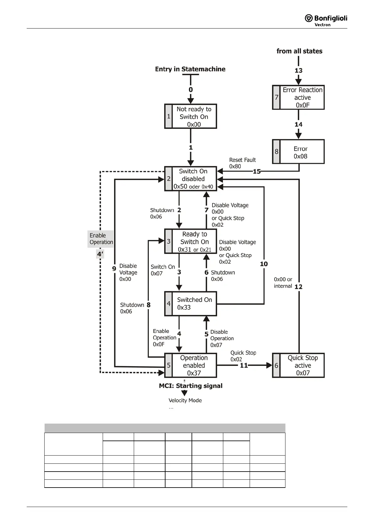
16.4.3.1 State machine diagram
The device control commands are triggered by the following bit pattern in the Control Word:
Control Word
Command
Bit 7 Bit 3 Bit 2 Bit 1 Bit 0
Transitions
Reset Fault Enable
Operation
Quick
Stop
Enable
Voltage
Switch
On
Shutdown X X 1 1 0 2, 6, 8
Switch On X 0 1 1 1 3
Switch On X 1 1 1 1 3
Disable Voltage X X X 0 X 7, 9, 10, 12

 Loading...


