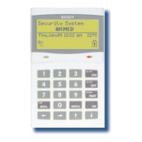
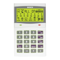
Solution 6000
Installation Manual Programming Overview
4-8
Bosch Security Systems 07/14 BLCC610I
3 Inputs 4 Outputs 5 Comms
3-0 Commands 4-0 Commands 5-0 Commands
AUMI 3-0-0 Zone Status AUMI 4-0-0 Output Status UMI 5-0-1 Call /Answer RAS
MI 3-0-1 Zone Array UMI 4-0-1 Turn Output On/Off MI 5-0-2 Call Forward On/Off
UMI 3-0-2 Bypass Zones MI 4-0-2 Output Array MI 5-0-3 Check Web Email
MI 3-0-3 Set Chime Zones MI 4-0-3 Door Status MI 5-0-4 Email System Log
MI 3-0-4 Set Part 2 Zones MI 4-0-4 Door Array MI 5-0-5 Start Direct Link
UMI 3-0-5 Smoke Sensor Reset MI 4-0-5 Door Override MI 5-0-6 Voice Setup
MI 5-0-8 Register Customer
3-1 Zone Properties 4-1 Properties I 5-0-9 Register Installer
MI 3-1-0 Zone Name MI 4-1-0 Output Name
I 3-1-1 Zone Type I 4-1-1 Event Type 5-1 Telephone Numbers
I 3-1-2 Area Assignment I 4-1-2 Event Assignment I 5-1-0 Number Prefix
I 3-1-3 Pulse Count I 4-1-3 Output Polarity MI 5-1-1 Destination 1
I 3-1-4 Pulse Count Time I 4-1-4 Time Parameter MI 5-1-2 Destination 2
I 3-1-5 Door Assignment I 4-1-5 Output Options MI 5-1-6 Call Forward On
I 3-1-6 Report Route MI 5-1-7 Call Forward Off
I 3-1-7
Report Options 4-2 Door Properties
I 3-1-8 Zone Options MI 4-2-0 Door Name 5-2 Properties
I 4-2-2 Unlock TimeZone I 5-2-0 Call Attempt Count
3-3 RF Zone I 4-2-3 Door Options I 5-2-1 Dialler Options
I 3-3-0 Add RF Device I 5-2-2 Phone Line Options
I 3-3-1 Delete RF Device 4-9 Output Testing I 5-2-3 Country
I 3-3-2 Test RF Device MI 4-9-0 External Siren Test I 5-2-7 Set SMS Password
MI 4-9-1 Internal Siren Test
3-4 Global Input Options MI 4-9-2 Strobe Test 5-3 Remote Access
I 3-4-0 EOL Value MI 4-9-3 Fire Siren Test I 5-3-0 Call Back Number
I 3-4-1 Keyswitch Options I 5-3-1 RAS Security PIN
I 3-4-2 Input Options I 5-3-2 Log Threshold
I 5-3-3 Ring Count
3-5 PGM Input I 5-3-4 RAS Options
I 3-5-0 Input Type I 5-3-5 DTMF Options
I 5-3-6 Voice Access Code
3-6 Tamper Inputs I 5-3-7 CLI Numbers
I 3-6-0 Tamper Options I 5-3-8 User RAS PIN
3-9 Input Testing 5-4 Reporting
UMI 3-9-0 Walk Test All Zones I 5-4-0 TX Format Dest 1
UMI 3-9-1 Walk Test A Zone I 5-4-1 TX Format Dest 2
I 3-9-2 Sensor Watch Time I 5-4-2 Test Route
I 5-4-3 System Route
I 5-4-4
Emergency Route
I 5-4-5 Swinger Dialler
I 5-4-6 Burg Report Delay
I 5-4-7 Fire Report Delay
5-5 MyAlarm
I 5-5-0 IP Address
I 5-5-1 IP Port
I 5-5-2 MyAlarm Options
I 5-5-7 Gateway Numbers
MI 5-5-8 Email Address
MI 5-5-9 Email Options

 Loading...


