11
4 5
6
3
21
21
5
43
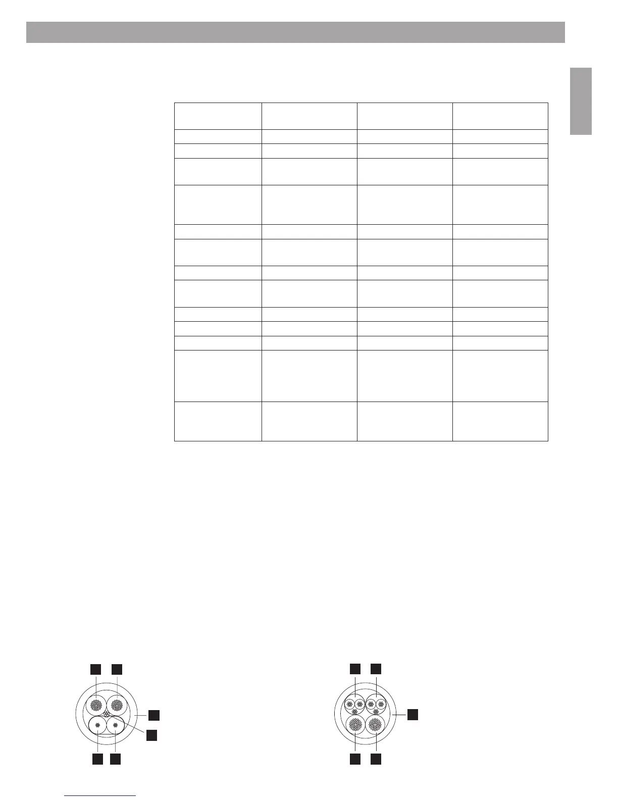
3.4 User interfaces connections
ControlSpace
®
AMS-8
Wall Controller
ControlSpace
®
AMS-8
Paging Panel
ControlSpace
®
AMS-8
Local Input Module
Power supply
Voltage 12-24VDC, +/-20% 12-24VDC, +/-10% 24VDC, +5%/-10%
Current @ 12VDC 50mA typ
@ 24VDC 30mA typ
@ 12VDC 140mA typ
@ 24VDC 70mA typ
@ 24VDC 60mA typ
Recommended power
supply*
BOSE CS AMS-8
24VDC, 2.7A stabilised
power supply
BOSE CS AMS-8
24VDC, 2.7A stabilised
power supply
BOSE CS AMS-8
24VDC, 2.7A stabilised
power supply
RS485 wiring**
Max Distance
(/with Hub)
600m
(1200m)
600m
(1200m)
Not applicable
Termination *** 120ohm 120ohm Not applicable
Cable type 1 pair twisted and
shielded
1 pair twisted and
shielded
Not applicable
Nom. Cap. 40pF/m Nom. Cap. 40pF/m Not applicable
Nom. Imp. 124ohm Nom. Imp. 124ohm Not applicable
Nom. Att. 2dB @ 1MHz Nom. Att. 2dB @ 1MHz Not applicable
Recommended cable BOSE CS AMS-8
communication/
power cable (blue) for
CS-WC/CS-PP
BOSE CS AMS-8
communication/
power cable (blue) for
CS-WC/CS-PP
Not applicable
Audio wiring Not applicable Standard Mic/Line cable,
1 pair with shielding
Bose CS AMS-8
audio/power cable
for (yellow) CS-LIM
* NOTE: If the above mentioned power supply is not used, any other power supply used in Europe must be
compliant with EN/IEC 60950.
** Required RS485 wiring
Always connect the components in a daisy-chain configuration (rather than in a star or other configuration). Star
wiring is only allowed using the CS-HUB. Be sure to separate the data cable from power wiring (>50V) on the
cable tray or other cable management.
*** Termination
The termination jumper should be placed on the last user interface (CS-WC or CS-PP), located at the end of each
RS485 communication line.
CS AMS-8 communication/power cable
1. Blue = RS485 communication ‘+’
2. Clear = RS485 communication ‘–’
3. Drainwire = RS485 communication ‘GND’
4. Red = power ‘24VDC’
5. Black = power ‘ground’
6. Blue jacket
CS AMS-8 audio/power cable
1. Yellow = balanced line cable (shielded)
2. Green = balanced line cable (shielded)
3. Red = power ‘24VDC’
4. Black = power ‘ground’
5. Yellow jacket
3. System Installation

 Loading...