67
4 5
6
3
21
21
5
43
3.4 Anschlüsse der Benutzerschnittstellen
ControlSpace
®
AMS-8
Wandbedienfeld
ControlSpace
®
AMS-8
Sprechstelle
ControlSpace
®
AMS-8
lokales Eingangsmodul
Stromversorgung
Spannung 12-24 VDC, +/-20% 12-24 VDC, +/-10% 24 VDC, +5%/-10%
Stromstärke @ 12 V DC 50 mA typ
@ 24 V DC 30 mA typ
@ 12 V DC 140 mA typ
@ 24 V DC 70 mA typ
@ 24 VDC 60 mA typ
Empfohlene
Stromversorgung*
BOSE CS AMS-8
24V DC, 2,7 A stabilisierte
Stromversorgung
BOSE CS AMS-8
24 V DC, 2,7 A
stabilisierte
Stromversorgung
BOSE CS AMS-8
24 V DC, 2,7 A
stabilisierte
Stromversorgung
RS485-Verkabelung**
Max. Entfernung
(/mit Hub)
600 m
(1200m)
600 m
(1200m)
Nicht anwendbar
Abschlusswiderstand*** 120 Ohm 120 Ohm Nicht anwendbar
Kabeltyp 1 Paar, verdrillt und
abgeschirmt
1 Paar, verdrillt und
abgeschirmt
Nicht anwendbar
Nennkap. 40 pF/m Nennkap. 40 pF/m Nicht anwendbar
Nennimp. 124 Ohm Nennimp. 124 Ohm Nicht anwendbar
Nom. Dämpfung 2 dB @
1MHz
Nom. Dämpfung 2 dB @
1MHz
Nicht anwendbar
Empfohlenes Kabel BOSE CS AMS-8
Kommunikations-/
Stromkabel (blau) für
CS-WC/CS-PP
BOSE CS AMS-8
Kommunikations-/
Stromkabel (blau) für
CS-WC/CS-PP
Nicht anwendbar
Audio-Kabel Nicht anwendbar Standard-Mic-/Line-Kabel,
1 Paar mit Abschirmung
Bose CS AMS-8 Audio-/
Stromkabel (gelb) für
CS-LIM
* Hinweis: Falls nicht die oben genannte Stromversorgung verwendet wird, muss in Europa jede andere
verwendete Stromversorgung der Richtlinie EN/IEC 60950 entsprechen.
** Benötigte RS485-Verkabelung
Schließen Sie die Komponenten stets in einer Daisy-Chain-Konfiguration an (und nicht in einer Stern- oder einer
anderen Konfiguration). Eine sternförmige Verkabelung ist nur mit dem CS-Hub zulässig. Achten Sie darauf, dass
das Datenkabel in der Kabelrinne oder einer anderen Kabelführung in jedem Fall von den Stromkabeln (>50 V)
getrennt ist
*** Abschlusswiderstand
Der Jumper für den Abschlusswiderstand sollte an der letzten Benutzerschnittstelle (CS-WC oder CS-PP)
angebracht werden, die sich am Ende jeder RS485-Kommunikationsleitung befindet.
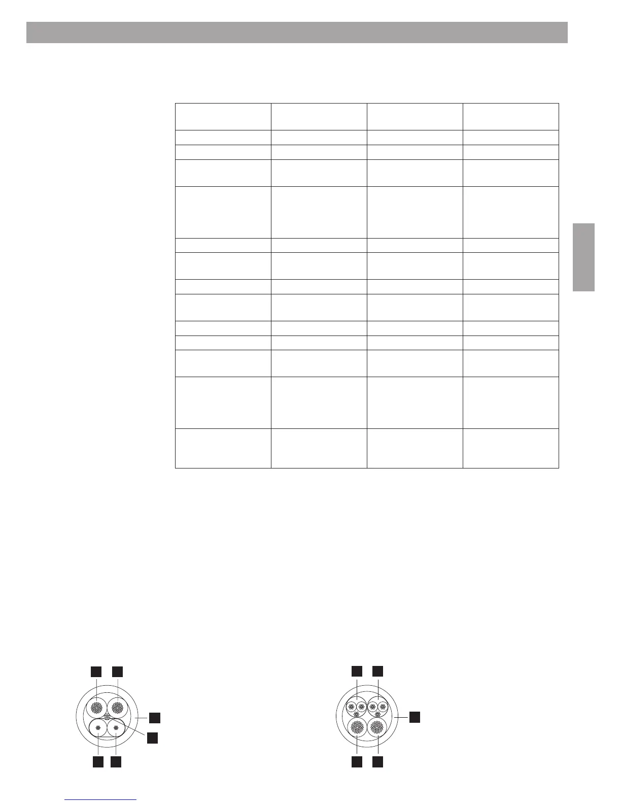
Kabel für Anschluss CS-WC/CS-PP
1. Blau = RS485 Kommunikation ‘+’
2. Hell = RS485 Kommunikation ‘–’
3. Drain-Wire = RS485 Kommunikation ‘GND’
4. Rot = Strom ‘24 V DC’
5. Schwarz = Strom ‘Erde’
6. Blaue Ummantelung
Kabel für Anschluss CS-LIM
1. Gelb = symmetrisches Line-Kabel
(abgeschirmt)
2. Grün = symmetrisches Line-Kabel
(abgeschirmt)
3. Rot = Strom ‘24 V DC’
4. Schwarz = Strom ‘Erde’
5. Gelbe Ummantelung
3. Installation des Systems
 Loading...