Brocade MLXe Series Hardware Installation Guide 107
53-1003030-01
Installing a Brocade MLXe-32 router
2
6. Tighten the screws at each end of the module faceplate by pushing them in and turning them
clockwise. Complete the tightening process using the flat-blade screwdriver.
7. Enter the write memory command to ensure that the slot will be correctly configured for the
new module after a reboot.
Brocade(config)# write memory
Write startup-config done.
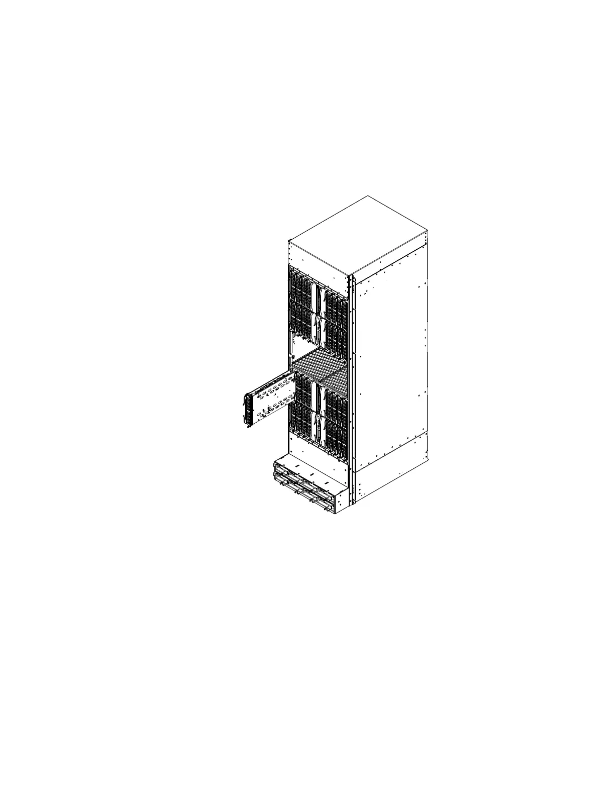
FIGURE 76 Installing a module in a Brocade MLXe-32 router
Power supply requirements for NI-MLX-1Gx48-T-A modules
You can install up to twenty NI-MLX-1Gx48-T-A modules and populate the remaining slots with other
modules, which requires four 2400W power supplies. You can achieve 4+4 power redundancy by
installing four additional power supplies.
If you install 21 or more NI-MLX-1Gx48-T-A modules in your router, you will need a minimum of five
power supplies. You can achieve 5+3 power redundancy by installing three additional power
supplies.
Using the insertion and extraction tool
Due to the high density of cables that the Brocade MLXe-32 router can support, it may be difficult
to insert and remove the RJ45 and optical connectors. An insertion and extraction tool has been
provided in the Brocade MLXe-32 accessory kit to make this task easier. Refer to Figure 77.
 Loading...