206 Brocade MLXe Series Hardware Installation Guide
53-1003030-01
Replacing fan assemblies
6
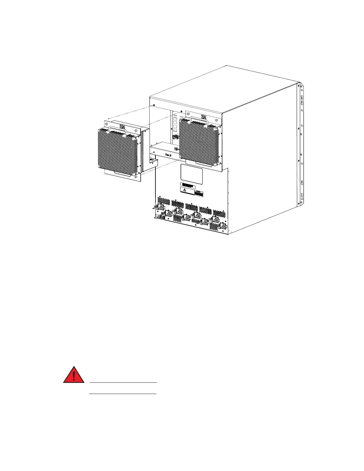
FIGURE 114 Replacing a fan assembly in a MLXe 16-slot router
4. Insert the new fan assembly into the slot and push the assembly in until the faceplate is flush
with the device. Pushing the assembly in seats the fan connector with the device connector.
5. Secure the fan assembly to the device by tightening the four captive screws.
6. Access the CLI, and enter the show chassis command to verify that both fans are operating
normally.
Replacing the fan tray assembly in 4-slot and 8-slot routers
The fan tray assemblies for Brocade MLXe 4-slot and 8-slot routers are accessible from the back of
the device.
You can remove and replace a fan tray assembly while the router is powered on and running.
To replace a fan tray assembly, have these items available:
• A new fan tray assembly, which you can order from Brocade.
• An ESD wrist strap with a plug for connection to the ESD connector on the router.
For safety reasons, the ESD wrist strap should contain a 1 megohm series resistor.
 Loading...