Brocade MLXe Series Hardware Installation Guide 123
53-1003030-01
Installing a Brocade MLXe-32 router
2
For the NEBS-compliant installation of 32-slot routers with AC and DC systems, use a ground wire
of at least 2 American Wire Gauge (AWG). The ground wire should have an agency-approved
crimped connector (provided with the device) attached to one end, with the other end attached to
building ground. The connector must be crimped with the proper tool, allowing it to be connected
to both ground screws on the enclosure. Before crimping the ground wire into the provided
ground lug, ensure the bare copper wire has been cleaned and antioxidant is applied to the bare
wire.
To ensure adequate bonding when attaching the ground lug, a minimum of 20 PSI of torque is
required to be applied to the mounting hardware used to attach the ground lug.
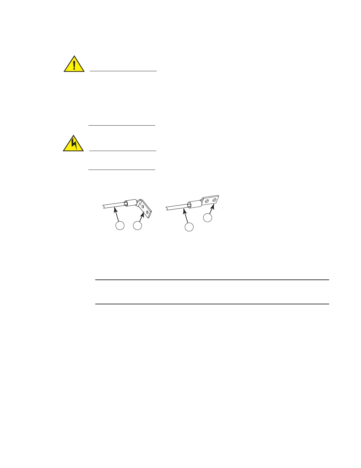
FIGURE 92 Crimping the power supply wire in the lug
4. Reconnect the power lugs to the power supply unit.
5. Connect the -48V wire to the negative terminal and the 0V wire to the positive terminal.
DC return must be isolated from the router ground (DC-I) when making connections to the
connections to the power supply.
6. Replace the safety cover. Refer to Figure 90.
This equipment installation must meet NEC/CEC code requirements. Consult local authorities for
regulations.
Removing Brocade MLXe-32 router DC power supplies
Follow these steps to remove a 2400W DC power supply in a Brocade MLXe-32 router:
1. Ensure the main DC power breaker is OFF.
2. Use a #1 Phillips screwdriver to remove screw that secures the safety cover, as shown in
Figure 90 on page 122. Remove the safety cover.
3. Use a #2 Phillips screwdriver to remove the screws securing the power lugs. Refer to Figure 91
on page 122.
4. Pull down on handle to remove power supply. Refer to Figure 88 on page 120.
1 AWG power supply wire:
for 2400W power supply, use#4 AWG
for 3000W power supply, use #2 AWG
2Power lug
 Loading...