Brocade MLXe Series Hardware Installation Guide 63
53-1003030-01
Installing a Brocade MLXe-8 router
2
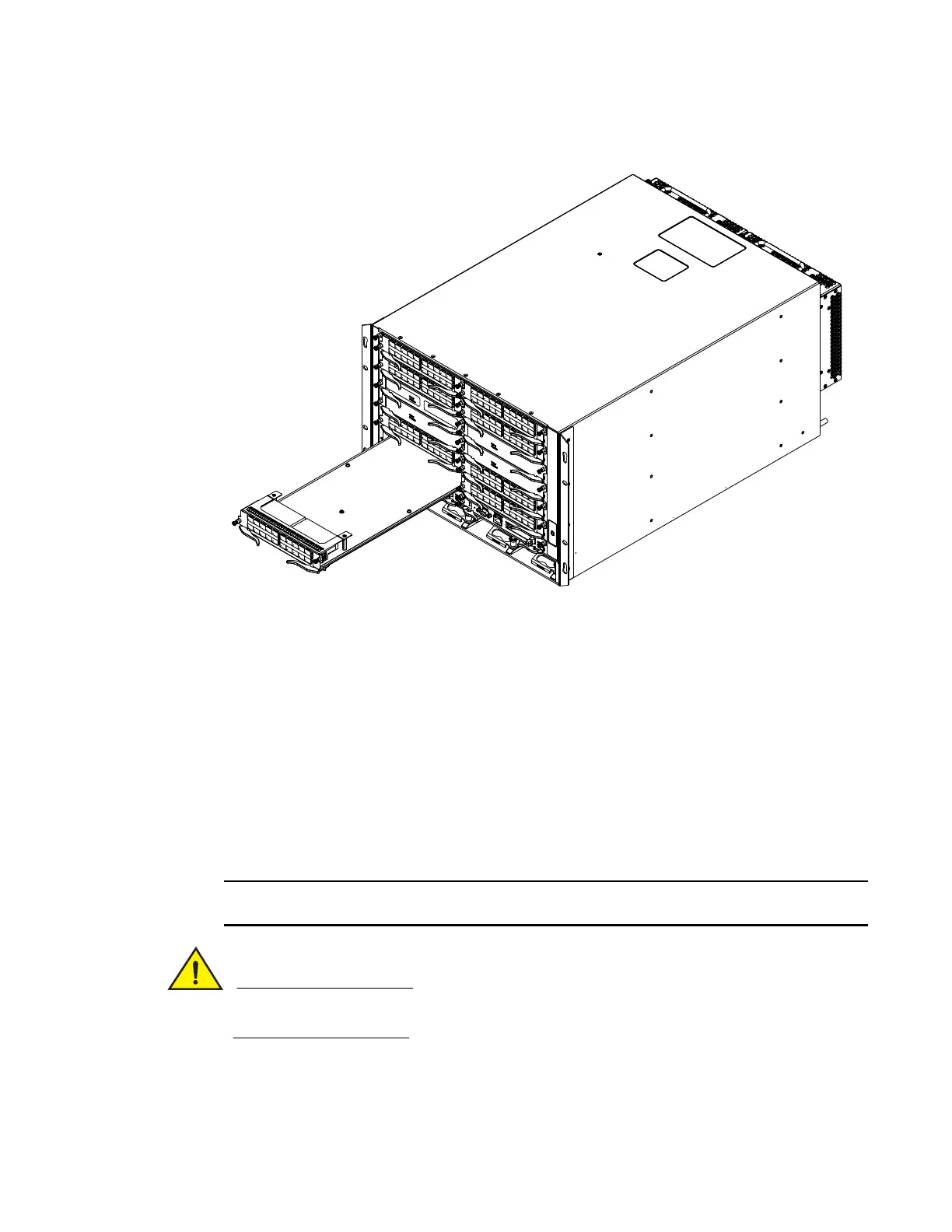
FIGURE 38 Installing a module in a Brocade MLXe-8 router
8. Rotate the ejectors flush with the module faceplate to fully seat the module in the backplane.
Modules have a snug fit for maximum EMI protection.
9. Tighten the two screws on each side of the module faceplate by pushing them in and turning
them clockwise. Complete the tightening process using a flat-blade screwdriver.
Installing power supplies in the Brocade MLXe-8 router
Follow these steps to install a power supply in the Brocade MLXe-8 router.
1. Remove the power supply slot blank.
2. Remove the power supply from the packaging.
3. Insert the power supply into the slot and slide it along the guides on each side of the slot. Refer
to Figure 39.
Empty power supply slots must be covered with slot blanks.
Carefully follow the mechanical guides on each side of the power supply slot and make sure the
power supply is properly inserted in the guides. Never insert the power supply upside down.
 Loading...