122 Brocade MLXe Series Hardware Installation Guide
53-1003030-01
Installing a Brocade MLXe-32 router
2
Follow these steps to connect a DC power source.
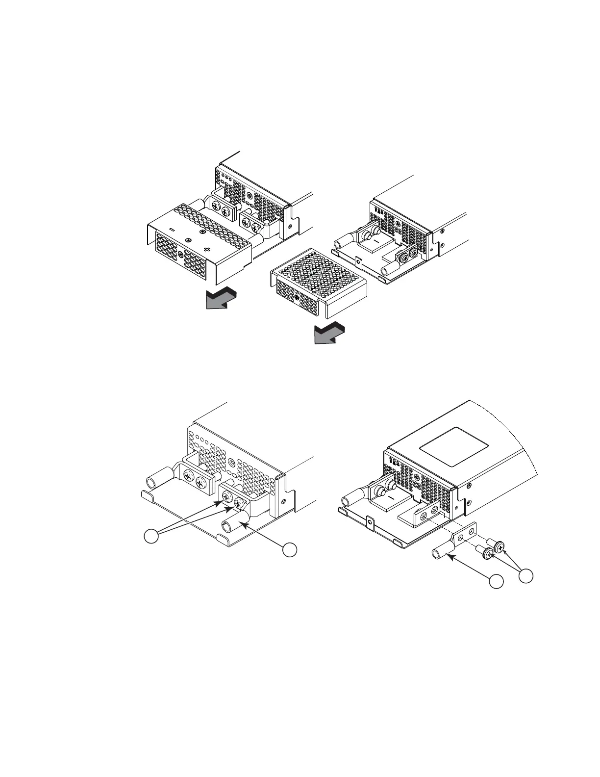
1. Use a #1 Phillips screwdriver to remove the screw that secures the safety cover, as shown in
Figure 90. Remove the safety cover.
FIGURE 90 Removing the safety cover (2400W power supply and 3000W power supply displayed)
2. Use a #2 Phillips screwdriver to unscrew the power lugs. Refer to Figure 91.
FIGURE 91 Removing the power lugs (2400W power supply and 3000W power supply displayed)
3. Crimp the correct AWG power supply wire into the power lugs.
For 2400W power supplies: #4 AWG power supply wire
For 3000W power supplies: #2 AWG power supply wire
Refer to Figure 92.
1 Power lug screws 2 Power lug
 Loading...