Brookeld Engineering Labs., Inc. Page 24 Manual No. M13-167
Manysamplesmustbecontrolledtoaspecictemperatureforviscositymeasurement.When
conditioningasamplefortemperature,besuretotemperaturecontrolthecontainerandspindle
aswellasthesample.
Pleaseseeourpublication,“MoreSolutionstoStickyProblems”,formoredetailrelatingto
sample preparation.
III.3 Selecting a Spindle/Speed
TheDV2Thasthecapabilityofmeasuringviscosityoveranextremelywiderange.Forexample,
theDV2TRVcanmeasureuidswithintherangeof100-40,000,000cP.Thisrangeisachieved
throughtheuseofseveralspindlesovermanyspeeds.SeeAppendixBfordetails.
Theprocessofselectingaspindleandspeedforanunknownuidisnormallytrialanderror. An
appropriate selection will result in measurements made between 10-100 on the instrument %
torque scale.Twogeneralruleswillhelpinthetrialanderrorprocess.
1)Viscosityrangeisinverselyproportionaltothesizeofthespindle.
2)Viscosityrangeisinverselyproportionaltotherotationalspeed.
Inotherwords:tomeasurehighviscosity,chooseasmallspindleand/oraslowspeed.Ifthechosen
spindle/speedresultsinareadingabove100%,thenreducethespeedorchooseasmallerspindle.
Experimentation may reveal that several spindle/speed combinations will produce satisfactory
resultsbetween10-100%.Whenthiscircumstanceoccurs,anyofthespindlesmaybeselected.
Non-Newtonianuidbehaviorcanresultinthemeasuredviscosityandyieldstresschangingifthe
spindleand/orspeedischanged.Seeourpublication,“MoreSolutionstoStickyProblems”,for
more details.
When viscosity data must be compared, be sure to use the same test methodology: namely the
same instrument, spindle, speed, container, temperature and test time.
DV2TLVViscometersareprovidedwithasetoffourspindlesand
anarrowguardleg;DV2TRVViscometerscomewithasetofsix
spindlesandawiderguardleg;DV2THAandDV2THBViscometers
comewithasetofsixspindlesandno guardleg. (See Appendix
Fformoreinformationontheguardleg.)
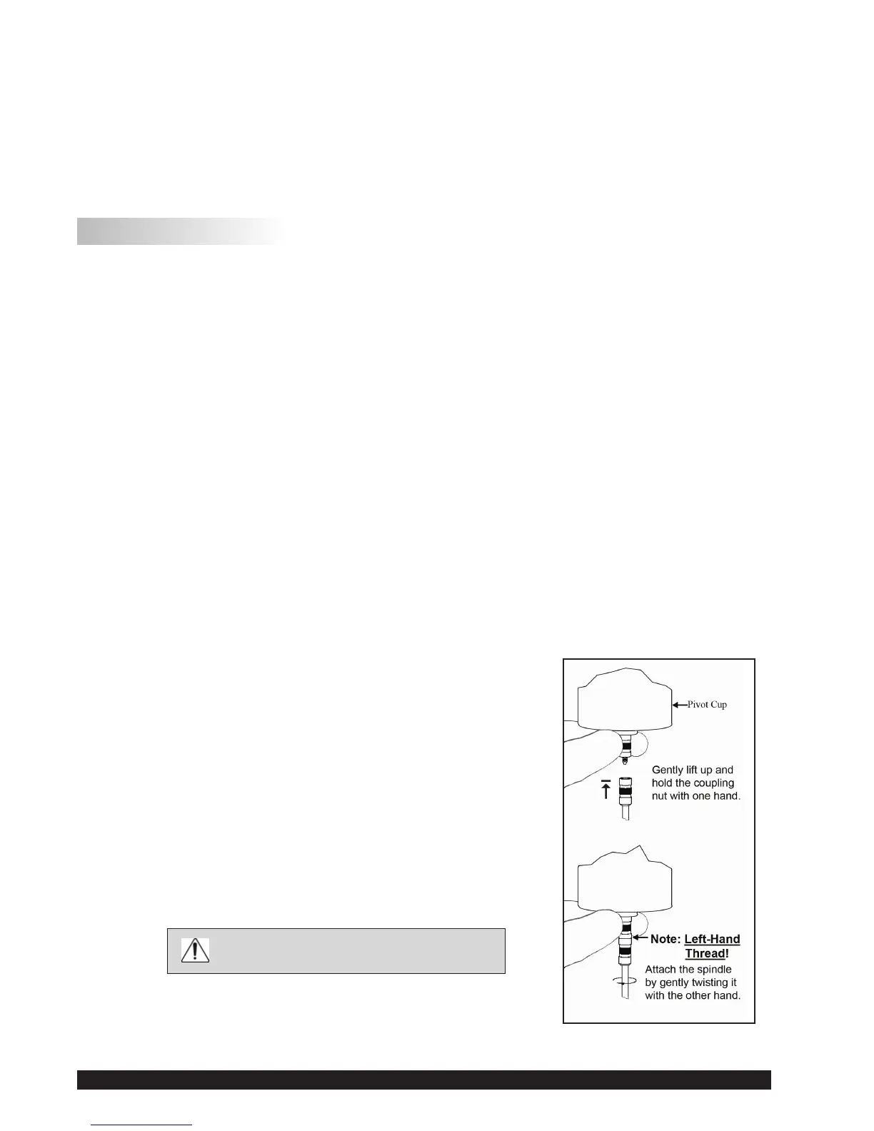
The spindles are attached to the viscometer by screwing them
ontothecouplingnutonthelowershaft(seeFigureIII-1).Note
thatthespindleshavealeft-handthread.Thelowershaftshould
besecuredandslightlyliftedwithonehandwhilescrewingthe
spindletotheleft.Thefaceofthespindlenutandthematching
surfaceonthelowershaftshouldbesmoothandcleantoprevent
eccentricrotationofthespindle.Spindlescanbeidentiedbythe
numberonthesideofthespindlecouplingnut.
ThemotorshouldbeOFF whenever
spindlesarebeingremovedorattached.
Figure III-1