Brookeld Engineering Labs., Inc. Page 59 Manual No. M13-167
Appendix A - Cone/Plate Viscometer Set-Up
ThisCone/Plate version ofthe DV2T usesthe same operatinginstruction procedures asdescribed
inthismanual.However,the“gap”betweentheconeandtheplatemustbeveried/adjustedbefore
measurementsaremade.Thisisdonebymovingtheplate(builtintothesamplecup)uptowardsthe
coneuntilthepininthecenteroftheconetouchesthesurfaceoftheplate,andthenbyseparating
(lowering)theplate0.0005inch(0.013mm).
WhenoperatingtheCone/Plateatelevatedtemperature,thegapmustbesetwiththecupandspindle
equilibratedatthetemperaturerecommended.MaximumtemperatureforCone/Plateoperationis80ºC.
Maximum operational temperature of sample cup is 100ºC.Personalprotectionisrecommendedwhen
controllingtotemperaturesabove80ºC.
Note: MicrometerAdjustmentRingwillbecomehotwhencontrollingsample
cupattemperaturesabove50ºC.
ProgrammableDV2TCone/PlateViscometers,S/N50969andhigher,haveanElectronicGapSetting
feature.Thisfeatureenablestheusertoeasilyndthe0.0005inchgapsettingthatwasestablishedat
Brookeldpriortoshipment.
ThefollowinginformationexplainshowtosettheElectronicGapandverifycalibrationoftheDV2T
Viscometer.
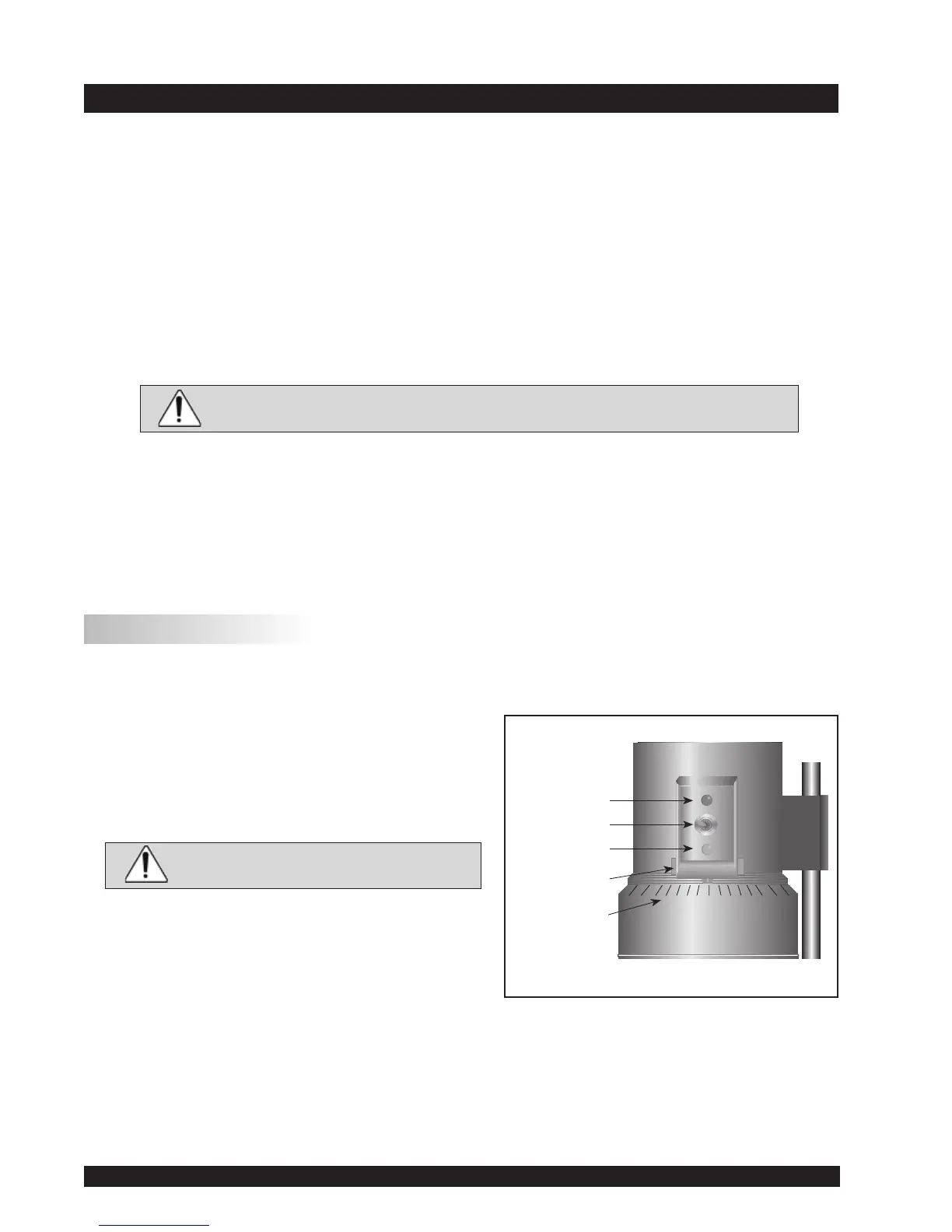
A.1 Electronic Gap Setting Features
TOGGLE SWITCH allows you to enable/disable the
ElectronicGapSettingFeature:leftpositionisOFF
(disabled),rightpositionisON(enabled).
PILOT LIGHT isthered(LED)light;whenilluminated,
itmeanstheElectronicSettingFunctionissensing
(enabled).
Note: Be sure the light is off before
introducingthetestsample.
CONTACT LIGHTistheyellow(LED)light;whenitrst
turnson,the“hitpoint”hasbeenfound.
SLIDING REFERENCE MARKERisusedafterndingthe
“hit point;” it is the reference for establishing the
0.0005inchgap.
MICROMETER ADJUSTMENT RINGisusedtomovethecupupordowninrelationtotheconespindle.
Turningtheringleft(clockwise)lowersthecup;turningitright(counterclockwise)raisesthecup.
Eachlineontheringrepresentsonescaledivisionandisequivalentto0.0005inchmovementof
theplaterelativetothecone.
Pilot Light
(red)
Toggle Swtich
Contact Light
(yellow)
Sliding Reference
Marker
Micrometer
Adjustment Ring
Figure A-1