Brookeld Engineering Labs., Inc. Page 60 Manual No. M13-167
A.2 Setup
1. BesurethattheViscometerissecurelymountedto
theLaboratoryStand,leveledandzeroedwithno
coneorcupattachedand0%torqueisdisplayed.
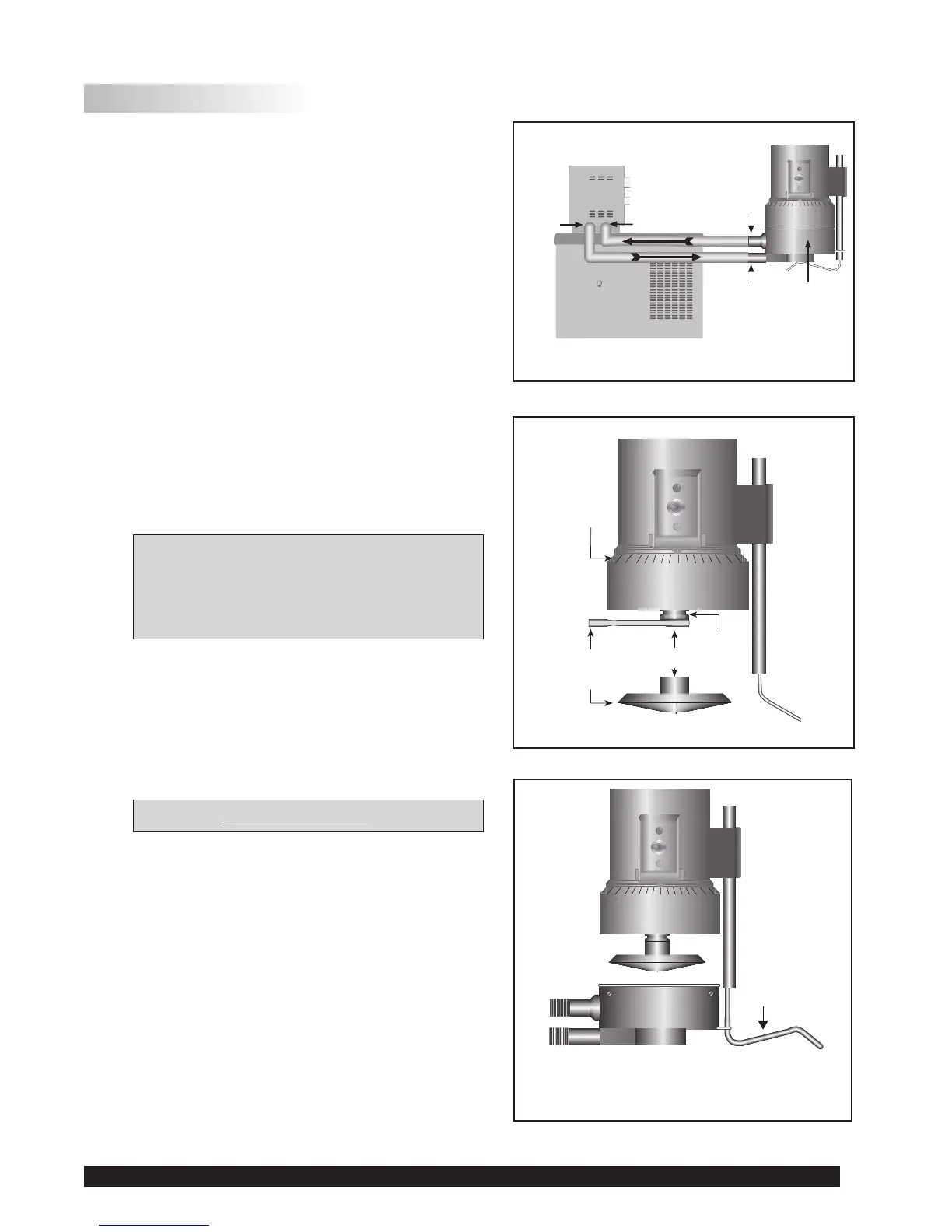
2. Figure A-2showsatypicalwaterbathsetup.Con-
nectthesamplecupinlet/outletportstothewater
bathinletandoutletandsetthebathtothedesired
testtemperature.Allowsufcienttimeforthebath
toreachthetesttemperature.
3. TheViscometerhasbeensuppliedwithaspecial
cone spindle(s) which contains the Electronic
GapSettingfeature.The“CPE”or“CPA”part
numberdesignationontheconespindleveries
theElectronicGapSettingfeature.
Note: The“CPE”or“CPA”coneorcup
cannotbeusedwithearlierDV2T
cone/plate Viscometers (below
S/N50969)whichdonothavethe
electronic gap setting feature.
4. With the motor off,thread the cone spindle by
usingthespindlewrenchtosecuretheviscometer
coupling nut (see Figure A-3);gentlypushupon
thecouplingnutandholdthissecurelywiththe
wrench.Threadtheconespindlebyhand.
Note: LeftHandThreads.
5. Attach the cup, taking care not to hit the cone
withthecup(Figure A-4),bypositioningthecup
againstthemicringandswingingthetensionbar
underthecup.Thetensionbarshouldhaveplastic
tubing in place.
Bath/Circulator
Bath
Inlet
Bath
Outlet
Sample
Cup
Cup
Outlet
Cup
Inlet
Figure A-3
Spindle
Wrench
Cone Spindle
These surfaces
must be clean!
Coupling Nut
Micrometer
Adjustment
Ring
Do Not hit the
CONE with the CUP!
Tension Bar
Figure A-2
Figure A-4