Installation and Operation Manual
X-VA-MT3809G-MT3810G-eng
Part Number: 541B182AAG
July, 2017
Models MT3809G & MT3810G
2-6 Electrical Connections to MT3809 with 4-20 mA/HART Transmitter, Alarms and Pulse Output
a) Before electrical connection, install the meter into the pipeline as
described in previous Section 2.5.
b) The electrical installation practice for conventional 4-20 mA and wired
HART devices is generally the same:
i. To avoid electrical interference and to meet the Electro Magnetic
Compatibilty (EMC directive) requirements, use individually shielded
twisted pair cable, either in single pair or multi-pair varieties. The
minimum conductor size is 0.51mm diameter (#24 AWG) for cable runs
less than 1,500 meters (@ 5,000 ft.) and 0.81mm diameter (#20 AWG)
for longer distances.
ii. In case of installation into explosion hazardeous environments it is
important to eliminate a potential incentive level of circulating current
through the cable shield in the event that there are local differences in
chassis ground potential between the two ends of the cable. Therefore,
able shields shall be connected to chassis ground (earth) in accordance
with the applicable national & regional installation codes and regulations.
A terminal screw inside the device allows for shield to chassis connection
in case the applicable installation regulation requires earthing at the
transmitter end.
iii. To prevent external interference, the signal loop should be grounded
at one point only. The single ground point will usually be at or near the
host (e.g. at the control system).
iv. Ensuring a properly specied power supply. Power for a two-wire
instrument loop is typically 24 Vdc. The voltage must be sufcient to
provide the necessary minimum voltage at the transmitter terminal. Take
into account voltage drops in the cable and load resistor, as well as from
any intrinsic safety barrier present. The transmitter could take up to 22
mA to indicate an alarm condition. Use this value to calculate the worst
loop voltage drop.
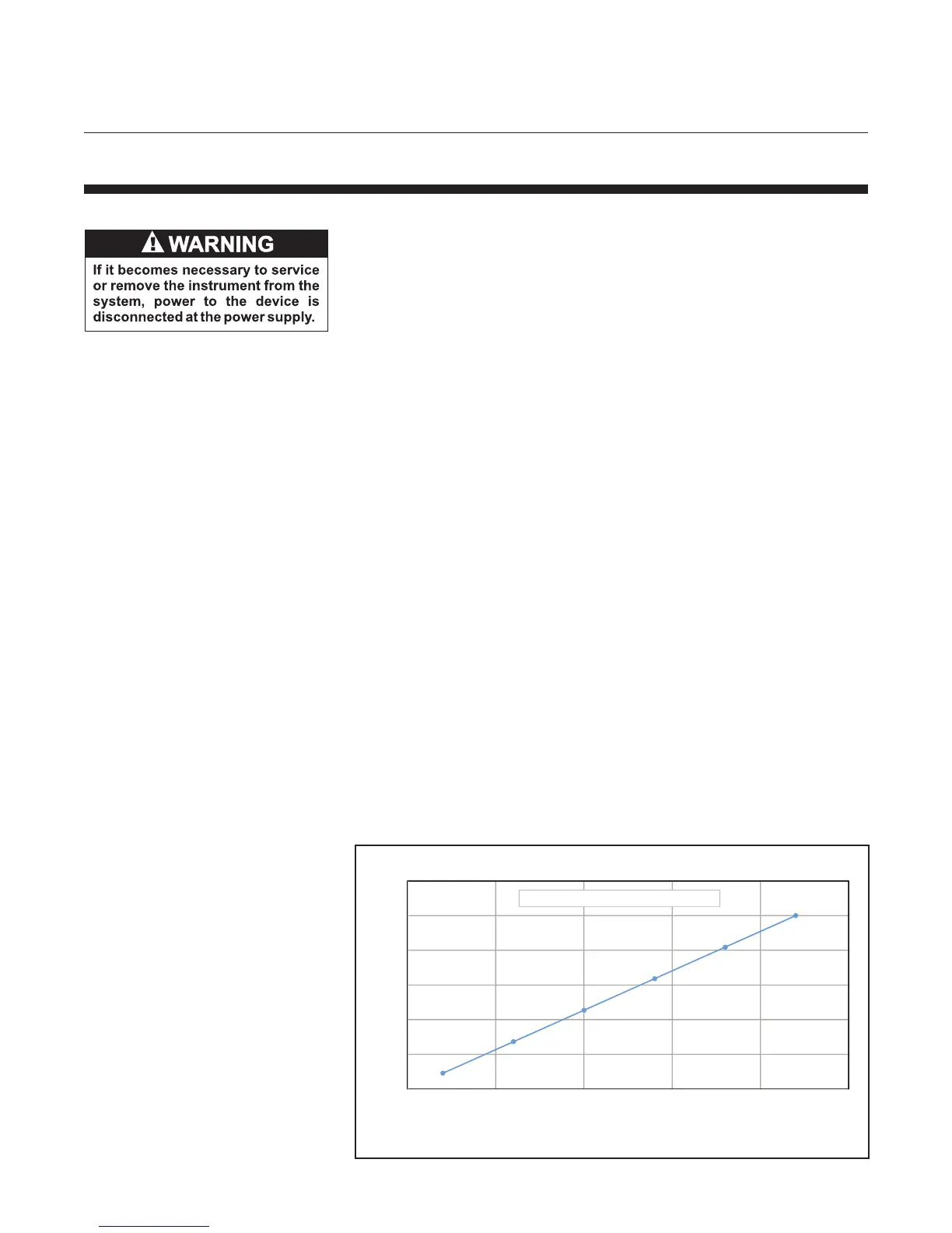
The maximum resistance of the loop resistor, the associated cable and
the barrier is determined by the power supply voltage and is shown
graphically in Figure 2-2.
Figure 2-2 Power Supply vs. Maximum Load Resistance
0
200
400
600
800
1000
1200
10 15 20 25 30 35
Loadresistanceɏ
Loopvoltage(V)
LoopVoltagevs.LoadResistance
Note: Load resistance should also include I.S. barrier resistance. When using HART communication,
the minum load resistance is 250 Ohms.
MaxLoop Resistance(ɏ)=45.5xvoltageͲ 455