Installation and Operation Manual
X-VA-MT3809G-MT3810G-eng
Part Number: 541B182AAG
July, 2018
Models MT3809G & MT3810G
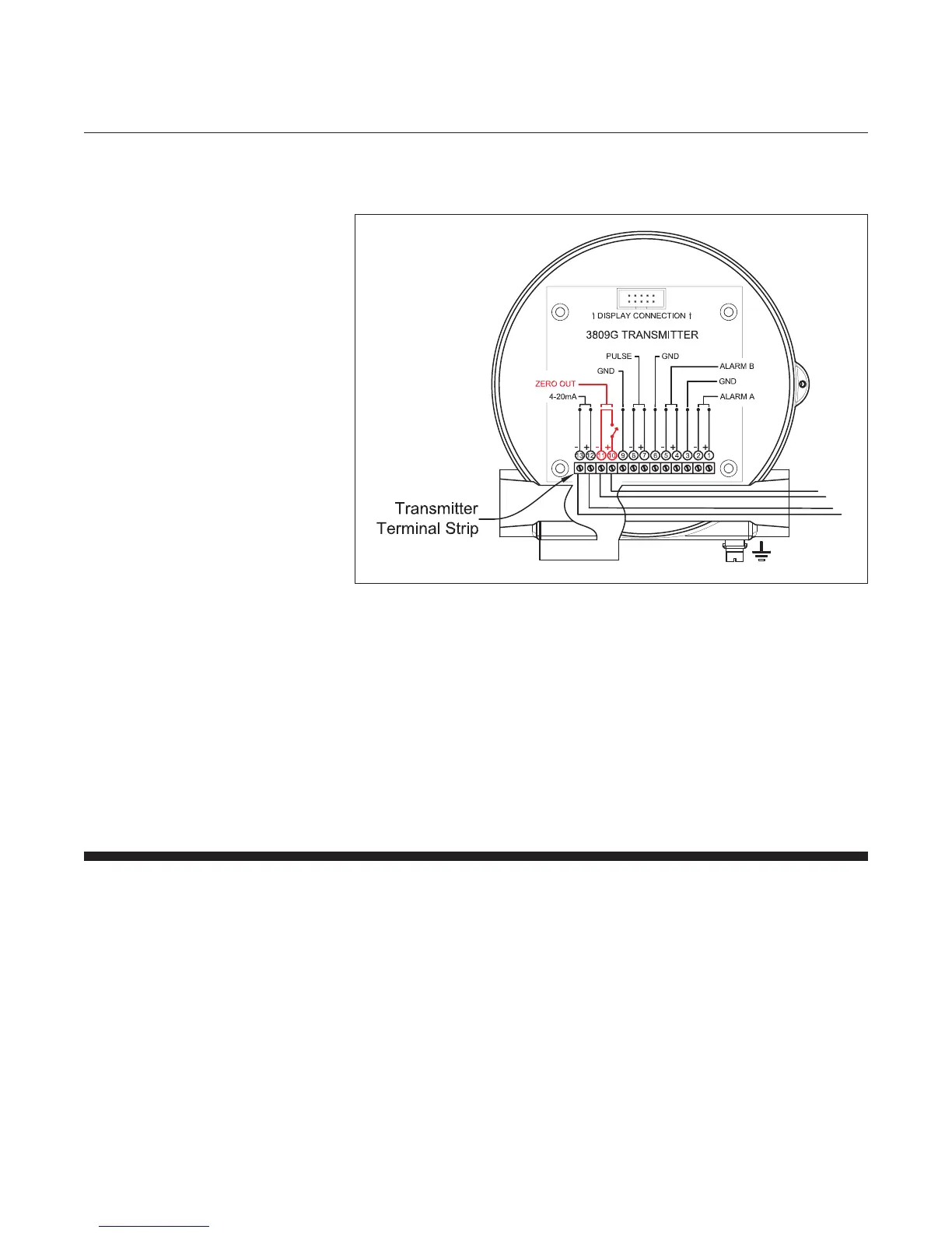
iii. Then, zero the transmitter shorting the two pins at the terminal block.
Reference Figure 2-4 below.
Figure 2-4 Transmitter Indicator Zero
Note: The zero function may be activated as part of a periodical
maintenance check. If desired, a zero switch can be remotely mounted
and wired to these terminals. The hazardous area classication will
determine the wiring methods used for this switch.
h) Under actual ow conditions, verify that the transmitter output matches
the mechanical pointer position. If a discrepancy is noted, the HART
communications channel can be used to verify or adjust the transmitter
settings.
repositioning the pointers.
2-9 Installation of the Model MT3809 Flowmeter with Transmitter and Digital Display and Inductive Alarms
a. Install the meter as described in Section 2-5
b. Install the transmitter as described in Section 2-6
c. Install the inductive alarms as indicated below Section 2-8