Installation and Operation Manual
X-VA-MT3809G-MT3810G-eng
Part Number: 541B182AAG
July, 2018
Models MT3809G & MT3810G
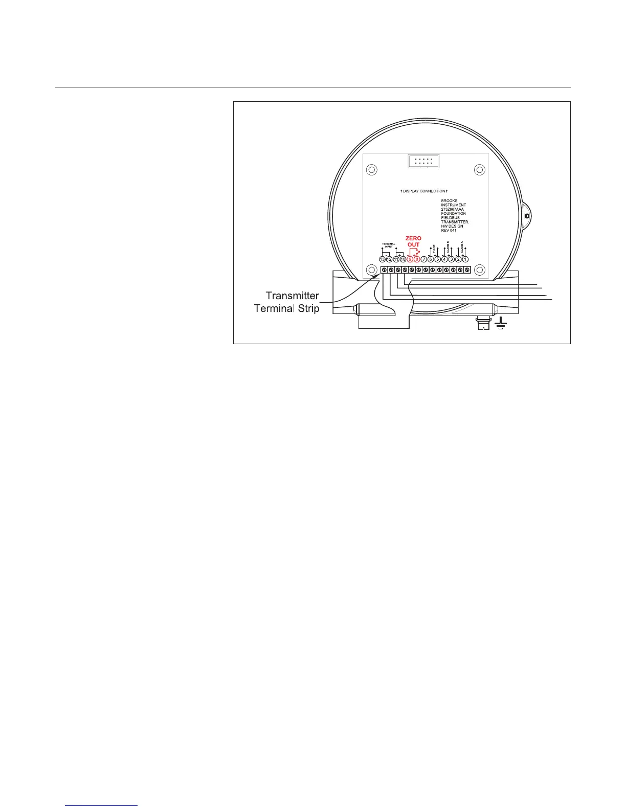
iii. Then, zero the transmitter shorting the two pins at the terminal block,
See Figure 2-11.
Note: The zero function may be activated as part of a periodical
maintenance check. If desired, a zero switch can be remotely mounted
and wired to these terminals. The hazardous area classication will
determine the wiring methods used for this switch.
h) Under actual ow conditions, verify that the transmitter output matches
the mechanical pointer position. If a discrepancy is noted, the Foundation
Fieldbus communication can be used to verify or adjust the transmitter
settings.
Transmitter with alarm and pulse output wiring connections:
The alarm contact and pulse output digital signals are electrically
identical, independent, optically coupled transistor outputs. Wiring will be
as required by the external driven system - Prover, DCS/PLC, terminal-
automation system, batch controller etc. These can be wired as an open
collector or open signal on the high or low side of voltage-rail within the
receiving equipment, depending upon the signal needs. When interfacing
to external electronics, be careful to work within the voltage/current
polarity and limits as specied in Section 1.
To install the typical transmitter alarms and/or pulse digital outputs
conguration:
i. Intrinsically safe installations require the use of barriers, power supply
limits and cable parameters. All connections are made in the transmitter
housing.
Refer to Table 1-12 in approvals section and Figures 2-5a/2-5b and
2-8a/2-8b.
ii. If the area classication is Division 2, barriers are not required and
cable parameters are not applicable. However, the electrical code will
require the use of conduit for wire protection.
Figure 2-11 Foundation Fieldbus Transmitter Indicator Zero