Installation and Operation Manual
X-VA-MT3809G-MT3810G-eng
Part Number: 541B182AAG
July, 2018
Models MT3809G & MT3810G
The oat is constructed with an integral magnet that activates a magnetic
sensor that is part of the transmitter. This same oat magnet also drives
the mechanical pointer. The ow rate is scaleable by setting independent
high and low range parameters. The analog output (AO) transmitter
parameters, AO Hi-Range and AO Lo-Range span the 4-20 mA signal. For
example, if ow rate is normally between 100 and 500 gpm, the AO Hi-
Range parameter is set at 500 and the AO Lo-Range is set at 100.
f) Typically applications require only the use of the 2 wire loop analog
signal. In some applications where transmitters and actuators are widely
separated (e.g. tank farms), devices are wired in a multi-drop conguration
to save wiring costs. Each unit is given an individual HART address to
distinguish each unit during communications over a common wire pair.
In this conguration, the 4-20 mA output signal cannot be used. Follow
the general HART foundation instructions for setting up a multi-drop
conguration.
g) After installation and powering of the loop, the transmitter must be
zeroed, both electrically and mechanically. This operation will compensate
for any stray magnetic effects in the vicinity of the transmitter.
Important: The zero adjusting of the pointer inuences the transmitter
indication, but not the other way around. Therefore, rst adjust the pointer
at the zero ow position, then the transmitter must be zeroed.
i. Flow must be veried to be zero during the entire zeroing.
ii. With the ow at zero and the oat at the zero ow position, adjust the
mechanical indicator to point to the ‘R’ (reference line) using the
adjustment screw on the face of the pointer, next to the hub.
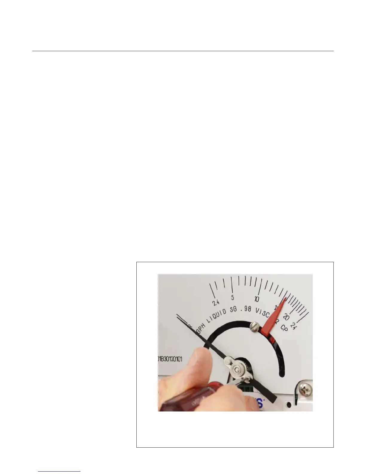
Figure 2-3 Mechanical Indicator Zero
Using a at blade screwdriver with a 1/8" blade, hold the pointer and
turn the screw to align with the “R” on the scale.
It may take a few adjustments to get the pointer on the “R”.