9.
Standard
adjustments
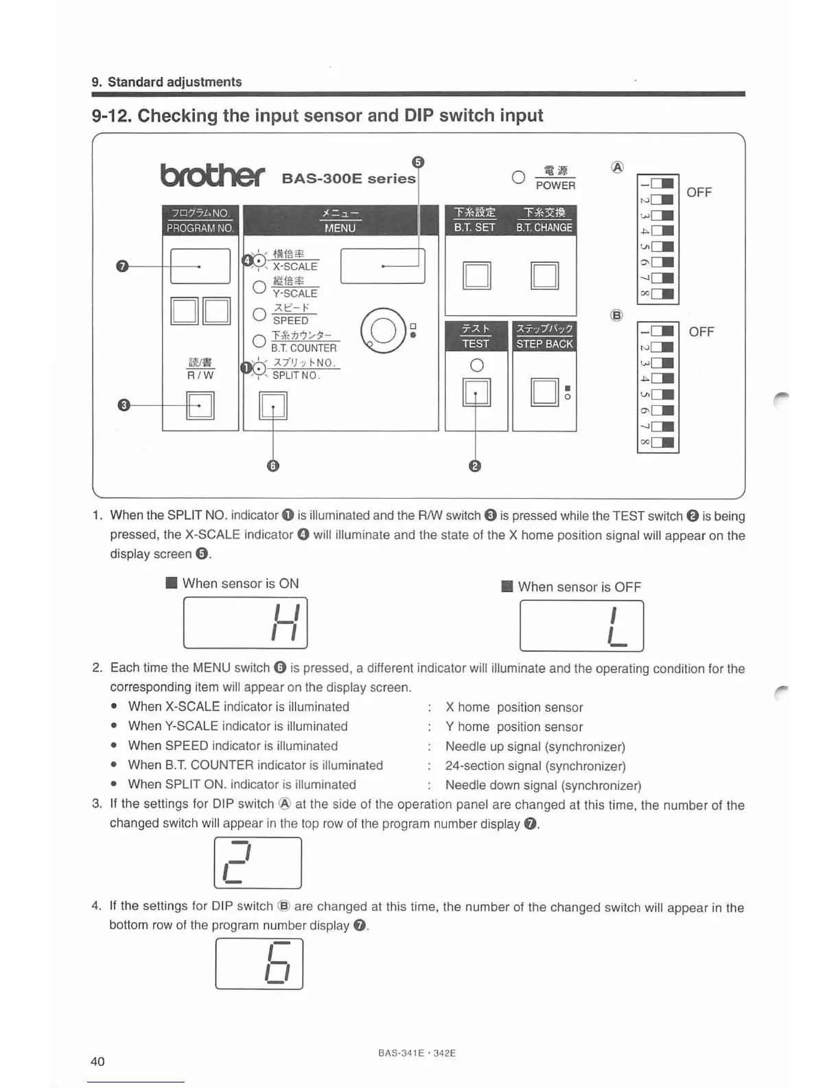
9-12. Checking the input sensor and DIP switch input
btotJler
BAS-300E
series
:~-=-~-
---
t/IENU
DO
-AI::'-
t-:
@~
0 SPEED
0 T-i'n'JrJ/11-
B.T
.
COUNTER
a)'CJ1J
R
/W
114
0 POWER
l'~~:i:E
"""F~x~
---
----
B.T.
SET
B.T.
CHANGE
D D
0
o
~
@
-
C.
OFF
N
C::.
w
C::.
-""C.
Vlc::.
~c.
-.JC::.
ooc::.
@
-C.
OFF
rv
C::.
wCII
-""LII
V>CII
o-CII
-.JCII
ooCII
1.
When the SPLIT
NO
. indicator 0 is illuminated and the R/W switch E)
is
pressed while the TEST switch
f)
is
being
pressed, the
X-SCALE indicator 0 will illuminate and the state of the X home position signal will appear on the
display screen
9.
• When sensor is ON
•
When sensor is OFF
,Y]
L]
2.
Each time the MENU switch 0 is pressed, a different indicator will illuminate and the operating condition for the
corresponding item
will appear
on
the display screen.
• When X-SCALE indicator
is
illuminated
X home position sensor
• When Y-SCALE indicator
is
illuminated Y home position sensor
• When
SP
EE
D indicator is illuminated Needle up signal (synchronizer)
• When
B.T.
COUNTER indicator
is
illuminated 24-section signal (synchronizer)
• When SPLIT ON. indicator
is
illuminated Needle down sig
na
l (synchronizer)
3.
If the settings for DIP switch
@a
t the side of the operation panel are changed at this time, the number of the
changed switch
wi
ll
appear
in
the top row of the program number display
e.
[U
4.
If the settings for DIP switch @ are changed at this time, the number of the changed switch will appear
in
the
bottom row of the program number
display
8.
LEJ
40
BAS·341 E ·
342E