3-32
Confidential
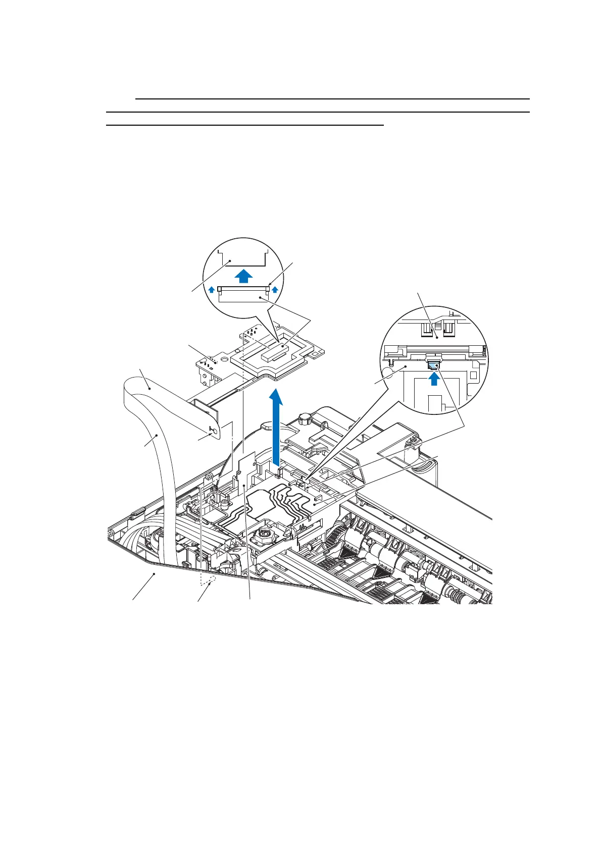
(10)Unlock the connector on the Carriage PCB and disconnect the Head flat cable.
Note After disconnecting the flat cable, check that each cable is not damaged at its end or
short-circuited. When connecting the flat cable, do not insert it at an angle. Lock the
connector, after confirming that the cable is not at an angle.
(11) Release the spring lock and slightly raise the Carriage PCB. Next, remove the
Carriage flat cable from the Cable guide of the Head/carriage unit (refer to the
illustration in page 3-39) and release the boss from the opening in the film (refer to the
illustration below).
(12)Take the Carriage PCB ASSY out of the Head/carriage unit and put it on the Upper
cover in front of the Head/carriage unit.
Head/carriage unit
Lock spring
Carriage PCB ASSY
Head flat cable
Carriage flat cable
Remove by pulling the lock
Carriage PCB ASSY
Head/carriage unit
Upper cover
Boss
Head flat cable
Opening
Film
Connector
 Loading...