III-1
CHAPTER III ELECTRONICS
3.1 OVERVIEW
3.1.1 Configuration of the Electronic Part
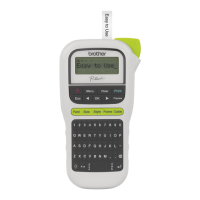
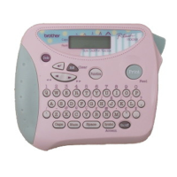
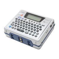
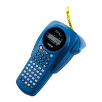
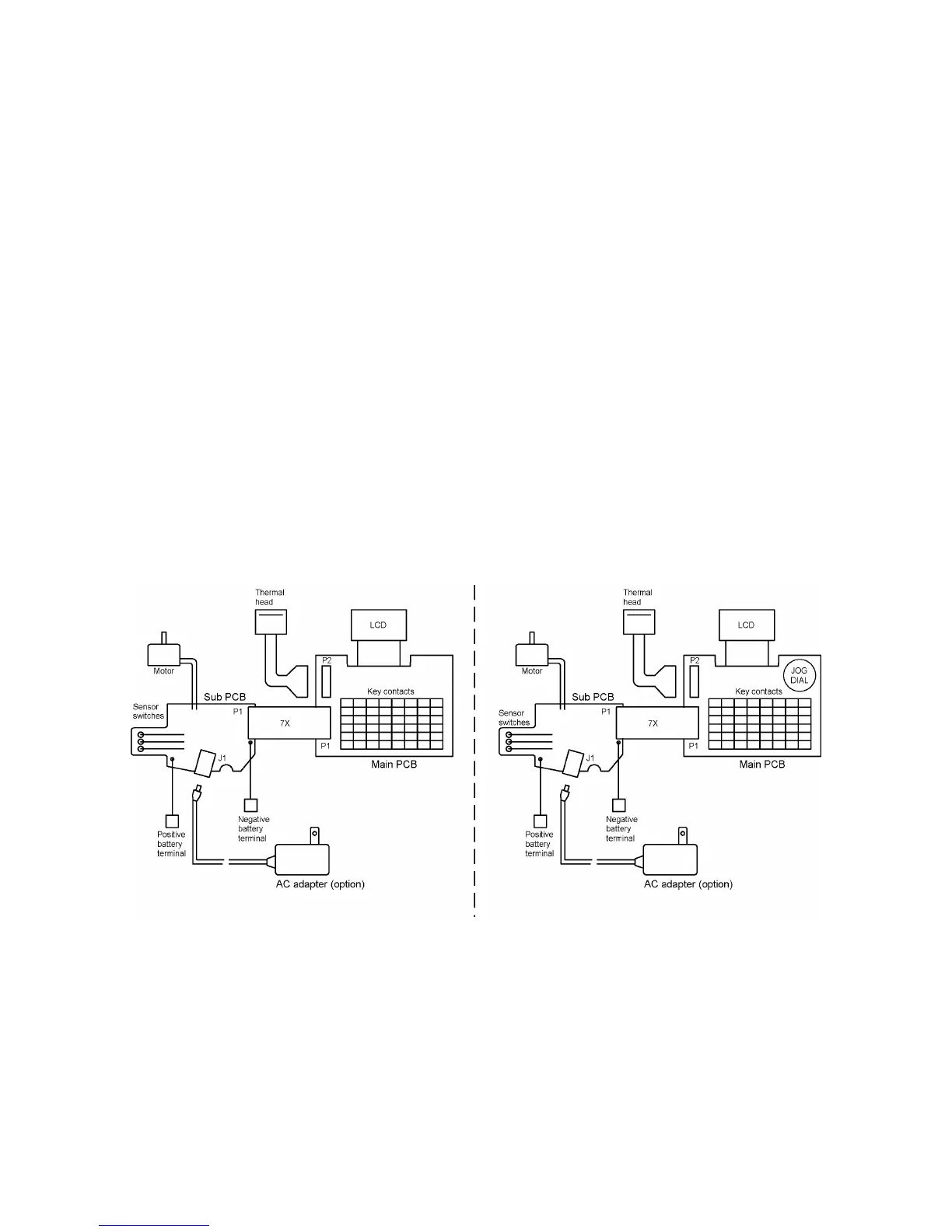
Fig. 3.1-1 shows a block diagram of the control electronics of the PT-1100/1130/1170/1180/11Q,
PT-1250/1160 and ST-1150. The control electronics consists of a printed circuit board (main PCB
+ Sub PCB), a motor, and a thermal head assembly.
3.1.2 Main PCB
This manages all the components including an LCD, keyboard, (Jog dial :PT-1250/1160 only) and
thermal head.
3.1.3 Sub PCB
Sub PCB consists of the sensor switches which identify the tape cassette type, governor circuit
which controls the rotation of DC motor, AC adapter jack and battery terminal.
(The AC jack is not provided for PT-1180.)
3.1.4 Motor
DC motor feeds tape.
3.1.5 Thermal Head
This is a thick film thermal print head which integrates a heat generator (consisting of 64 heating
elements vertically aligned) and drive circuit.
Fig. 3.1-1 Configuration of the Electronic Part
(PT-1100/1130/1170/1180/11Q/ST-1150) (PT-1250/1160)

 Loading...