EasyManuals Logo

Brother P-Touch PT-1180 Service Manual

Brother P-Touch PT-1180
83 pages
To Next Page IconTo Next Page
To Previous Page IconTo Previous Page
Page #67 background imageLoading...
Page #67 background image
III-9
3.2.5 Motor Control Circuit
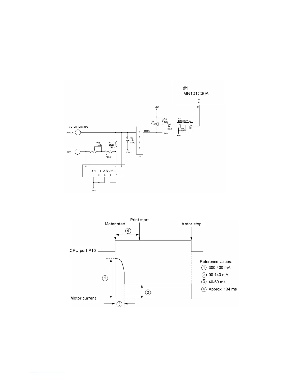
Fig. 3.2-11 shows the motor drive control of the DC motor which feeds tape.
Through P10, the CPU produces a start/stop control signal to the motor control circuit. Fig. 3.2-12
shows the part of motor waveforms.
#1 (BA6220) is electronic governor IC and controls to keep the rotation speed of motor constant
even if the power source voltage (VBT) varies.
Fig. 3.2-11 Motor Control Circuit
Fig. 3.2-12 Part of Motor Waveforms

Table of Contents

Other manuals for Brother P-Touch PT-1180

Questions and Answers:

Question and Answer IconNeed help?

Do you have a question about the Brother P-Touch PT-1180 and is the answer not in the manual?

Brother P-Touch PT-1180 Specifications

General IconGeneral
BrandBrother
ModelP-Touch PT-1180
CategoryLabel Maker
LanguageEnglish

Related product manuals