EasyManuals Logo

Brother P-Touch PT-1180 Service Manual

Brother P-Touch PT-1180
83 pages
To Next Page IconTo Next Page
To Previous Page IconTo Previous Page
Page #73 background imageLoading...
Page #73 background image
III-15
3.2.10 Cassette Sensor Circuit
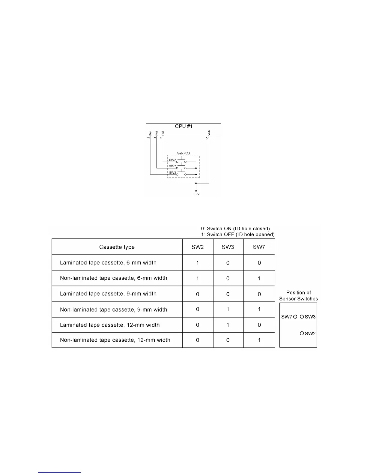
Fig. 3.2-20 shows the cassette sensor circuit. This circuit detects each of the five sensor switches
which is pushed or not depending upon the ID holes provided on a tape cassette currently
mounted.
By perceiving the states of those sensor switches, the CPU identifies the tape cassette type (the
varieties and the widths).
If an ID hole is open, the sensor switch is not pushed.
Table 3.2-1 lists the coded values for identifying the tape cassette type.
Fig. 3.2-20 Cassette Sensor Circuit
Table 3.2-1 Coded Values for Identifying Tape Cassette Type

Table of Contents

Other manuals for Brother P-Touch PT-1180

Questions and Answers:

Question and Answer IconNeed help?

Do you have a question about the Brother P-Touch PT-1180 and is the answer not in the manual?

Brother P-Touch PT-1180 Specifications

General IconGeneral
BrandBrother
ModelP-Touch PT-1180
CategoryLabel Maker
LanguageEnglish

Related product manuals