III-11
3.2.7 Voltage Detection Circuit and Temperature Sensor circuit
Fig. 3.2-15 and Fig. 3.2-16 (See next page) show the voltage detection circuit and the ambient
sensor circuit which are composed of a resister combination.
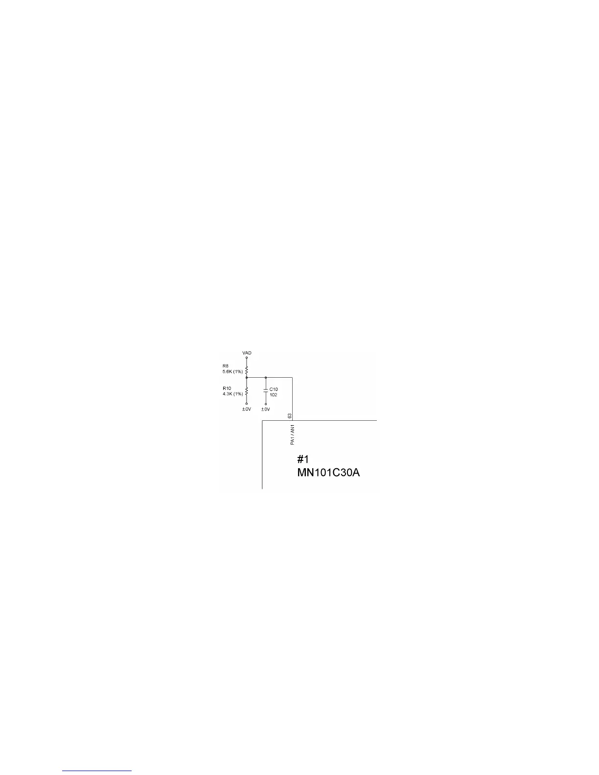
[ 1 ] Voltage detection circuit
This circuit, which is composed of divider resistors R8 and R10, steps down the power source VAD
fed from batteries or the AC adapter output and feeds the output to the A/D input port PA1 on the
CPU. According to the drive source voltage, the CPU determines the optimum head drive power.
During non-printing:
If the voltage level of the VAD drops below approx. 6.8V, the CPU immediately shuts down the
power.
During printing:
• If the voltage level of the VAD rises over approx. 10.8V, the CPU immediately shuts down the
power.
• If it drops even more below approx. 5.3V, the CPU displays the message to warn you of a low
battery after completion of printing.
• If it drops even more below approx. 5.0V, the CPU interrupts the printing and displays the
message to warn you of a very low battery.
• If it drops below approx. 4.8V, the CPU immediately shuts down the power.
Fig. 3.2-15 Voltage Detection Circuit

 Loading...