188
COOLING SYSTEM
OPERATION
OPERATION
All models use a two-stage cooling system
design. The cooling system is dependent on water
pump pressure and controlled by thermost at and
pressure valve operation.
Restricted or inadequate water flow
through the outboard reduces cooling system
performance and ma y lead to seve re power-
head damage.
Cylinder Block / Cylinder Head
Cooling
The flow of water throu gh the cylinder block and
cylinder he ads is co ntrolled by two thermo stats
and one external pre ssure va lve. The p ressure
valve is connected by hoses to the top of each cyl-
inder head.
The thermost ats an d pressure valve control the
flow of water entering the vertical water passages
of the cylinder heads.
At low speed , th e pressure valve is against t he
seat and the thermostats are closed. Warm water
from the cylinder block gr adually migra tes to t he
thermostat pocket at the to p of each cylind er
head.
The thermostat opens when the wa ter tempe ra-
ture reaches approximately 143°F (62°C).
When th e th ermostat o pens, wate r flows down
through the cylinder head to a passage in the cyl-
inder block. Water flows throu gh the block to the
exhaust housing and then out of the outboard.
At higher sp eeds, wate r pressure op ens th e
pressure relief valve at approximately 1200 RPM.
Water f lows th rough the va lve and byp asses t he
thermostats. Hoses route the wate r flow from the
pressure va lve to t he vertical wat er p assages
below the thermostats. All water flows through the
cylinder heads to the outlet passages of the block
and then exits through the adapter housing.
This pressure contro lled wa ter outlet cir cuit pro-
vides a “high flow” discharge of water during high
speed operation.
This cooling syste m configuration provides “bal-
anced cooling” at h igher RPM by using one pres-
sure valve to contro l the discha rge of water
through both cylinder heads.
Additional Cooling
Two external water supply hoses direct water flow
into th e exhaust (plenum) are a of the cylinder
block. The water reduces exhaust runner temper-
atures and circulates through the cylinder block.
The base ga sket limits water flo w to th e ba se of
the block and divert s water flo w to the rear port
and rear starboard fittings of the adapter housing.
On 3.3 L mo dels, a t hird external wate r hose
directs water flow from the exhaust housing of the
cylinder block to a n exhaust passage a t t he
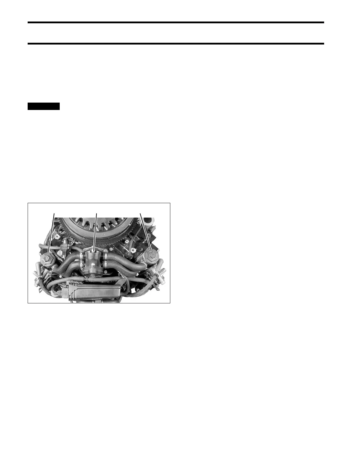
1. Thermostats
2. Pressure valve assembly
004269