95
ELECTRICAL AND IGNITION
SENSOR TESTS
6
Connect red meter lea d to terminal “A” and black
meter lead to terminal “C.” Rotate the sensor lever
through it s range of trave l. Resistance reading
must change evenly as the sensor lever is moved.
Connect red meter lead on terminal “B” and black
meter lea d to terminal “C.” Ro tate the sensor
lever. Resistance reading must chang e evenly as
the sensor lever is moved.
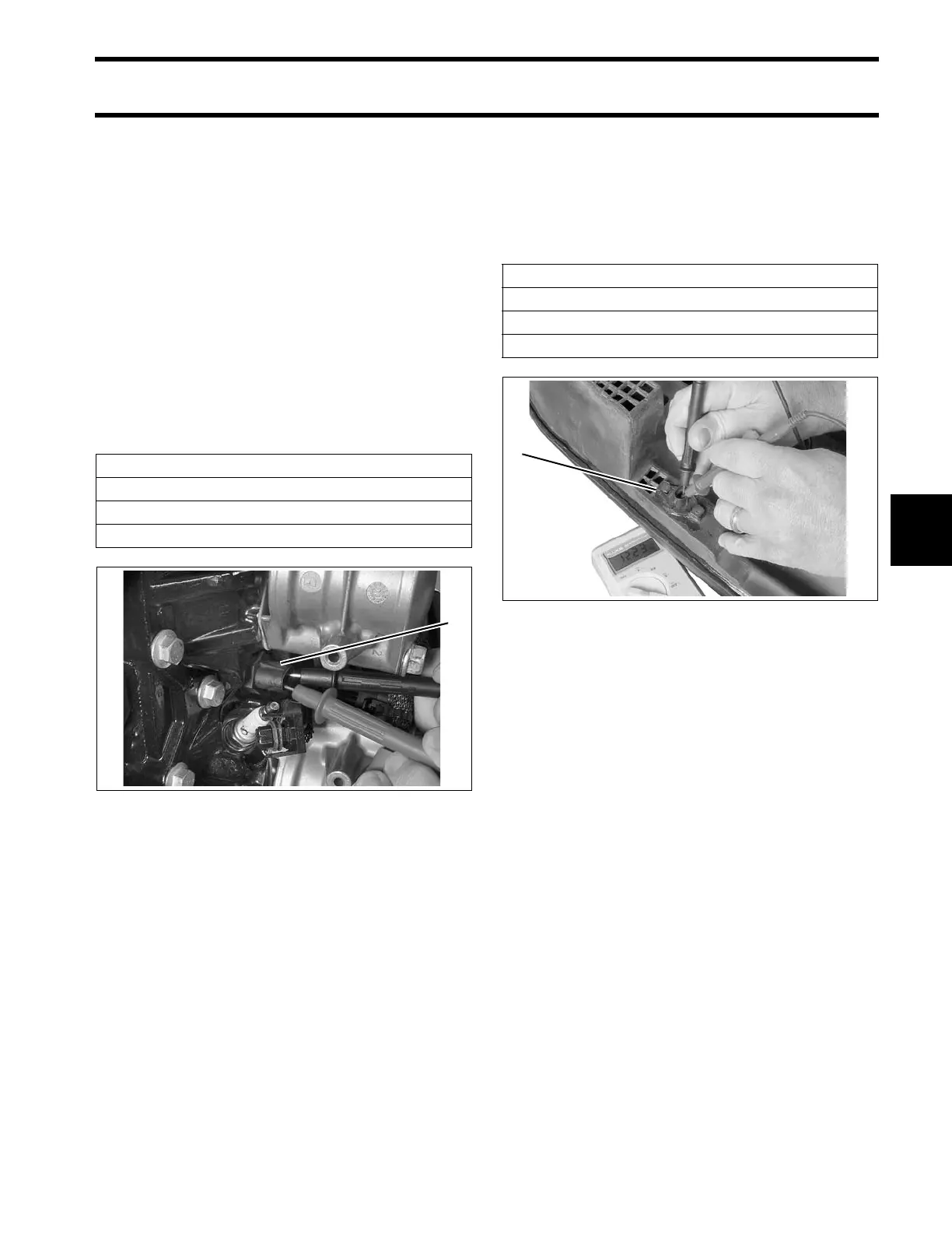
Engine Temperature Sensor Test
Remove the ele ctrical connector from the engine
temperature sensor.
Use a digital multimeter to measure sensor resis-
tance.
Air Temperature Sensor (AT) Test
Remove the electrical connector from the air tem-
perature sensor.
Use a digital multimeter to measure sensor re sis-
tance.
Knock Sensor Test
There are no te sts for the knock senso r. If
Evinrude Diagnostics reports Service Code 7 or 8,
replace with a new sensor.
Make sure sensor retaining screw is tightened to a
torque of 14 to 16 ft. lbs. (19 to 22 N·m).
Engine Temperature Sensor Resistance
680 Ω ± 5% @ 212°F (100°C)
10000 Ω ± 1% @ 77°F (25°C)
32654 Ω ± 2.5% @ 32°F (0°C)
1. Engine temperature sensor (2) 004196
AT Sensor Resistance
680 Ω ± 5.25% @ 212°F (100°C)
10000 Ω ± 1.5% @ 77°F (25°C)
32654 Ω ± 3.0% @ 32°F (0°C)
1. AT sensor 004216