91
ELECTRICAL AND IGNITION
ELECTRICAL HARNESS CONNECTIONS
6
ELECTRICAL HARNESS
CONNECTIONS
Inspect wiring and electric al connectio ns. Disas-
semble a nd clean all corrode d co nnections.
Replace damaged wiring, con nectors, o r termi-
nals. Rep air any shorted electrical circuits. Refer
to wirin g diagrams and refere nce ch arts for spe-
cific wiring details.
Refer to CONNECTOR SERVICING on p. 122.
Engine Harness to Stator
Connector
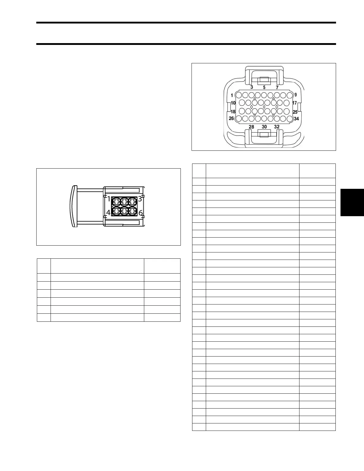
EMM J1-A Connector
004050
Pin
No.
Description of Circuit Wire Color
1 Stator winding (1S) Yellow
2 Stator winding (3S) Orange
3 Stator winding (2S) Brown
4 Stator winding (1F) Yellow /White
5 Stator winding (3F) Orange/White
6 Stator winding (2F) Brown/White
001875
Pin
No.
Description of Circuit Wire Color
1 Oil Pressure sensor Tan/White
2 Diagnostic connector Red
3 Diagnostic connector White
4 Ground, water in fuel (digital) Black
5 Oil level switch Tan/Black
6 Crankshaft position sensor (CPS) Yellow
7 Ground, CPS (digital) White
8 Bootstrap connector (programming) Blk/Orange
9 Stop circuit Blk/Yellow
10 Sensors 5 V Red
11 Ground (analog) Black
12 Engine temperature sensor, port Pink/Black
13 CANbus, NET-L Blue
14 CANbus, NET-H White
15 Water pressure Pink
16 Tachometer Gray
17 CHECK ENGINE signal, SystemCheck Tan/Orange
18 TPS Green
19 Engine temperature sensor, starboard Pink/Black
20 Air temperature sensor Pink/Blue
21 CANbus, NET-S Red
22 CANbus, NET-C Black
23 Water in fuel Pink/Green
24 NO OIL signal, SystemCheck Tan/ Ye ll ow
25 WATER TEMP signal, SystemCheck Tan
26 Start signal Yellow/Red
27 Ground, knock sensors Tan/Blue
28 vacant
29 Shift switch (shift linkage) Black/Yellow
30 Knock sensor, stbd Yellow/Green
31 Knock sensor, port Yellow/Blue
32 Trim sender, IN White/Tan
33 Trim sender, OUT White/Tan
34 LOW OIL signal, SystemCheck Tan/Black