23
.ROUTINE SERVICE
OUTBOARD RIGGING CONNECTIONS
2
For an I-Command oil level display, an accessory
CANbus oil level sende r must be inst alled in the
oil t ank. Co nnect the sender to the I-Command
network. Refer to the I-Command Digit al Net-
work Guide.
Use Evinrude Diagnostics software to adjust net-
work settings in th e EMM. From the Settings
screen, select Engine Options.
ICON Network Connections
If the outboard is equ ipped for an Evinrude ICON
control system, con nect the outboard to the net-
work as follows.
Refer to the ICON Rem ote Control Sys tem
Installation Guide.
Connect the buss cable from the rear network hub
to the outboard’s network harness.
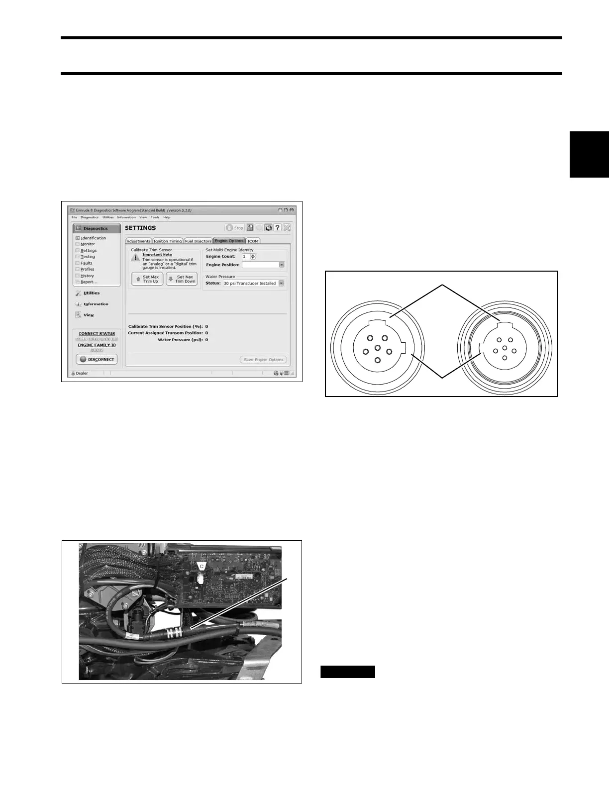
IMPORTANT: Do not force conn ectors or lock-
ing rings. Prop erly aligne d conne ctors a ssemble
easily.
Do not use Electrical Grease on ICON buss cable
connectors.
To assemble the connectors:
• Use the large t abs and small t abs to carefully
align buss cable connectors.
• Carefully align pins and socket s of conne ctors.
Do NOT force connectors together.
• Tighten locking rings of buss connectors fing er
tight. Do NOT use locking rings to force connec-
tors together.
Do not rot ate co nnectors un til t hey a lign. This
could result in a mismatched connection. It is pos-
sible for each pin to enter a socket even if the tabs
are misaligned. Look at the t abs to en sure con-
nector alignment prior to making the connection.
Engine Mo nitor information is distributed to an
ICON or I-Command network through th e ICON
gateway module. Refer to the I-Command Digital
Network Guide.
The ICON Harne ss an d Relay Kit, P/N 76529 6,
must be used to pro vide power to boat accesso-
ries that requ ire switched B+. This kit is used in
place of connecting accessories to the “A” termi-
nal o f th e key switch. Accessories connected to
the accessory power rela y sho uld not exceed 7
amps.
Do not connect boat accessories to
the key switch of an ICON system. Connecting
accessories to the key switc h can ca use low
Engine Options Screen 008563
1. ICON network connector 008001
1. Large tabs
2. Small tabs
007883