234
POWERHEAD
POWERHEAD ASSEMBLY
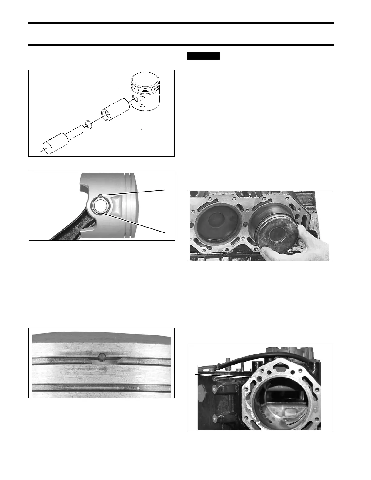
in each wrist pin hole. Gap of retaining ring faces
away from notch in piston.
Installing Pistons
When all pistons and connecting rods are assem-
bled, inst all piston rin g set s. Be sure rings are
installed in the cylinder used to test ring end gap.
Refer to POWERHEAD INSPECTION on p. 228.
IMPORTANT: Be su re ga p of ring fit s sq uarely
around dowel pin.
Before continuing, mak e sure that
all Gel-Seal II has been removed from the cyl-
inder blo ck and crank case ma ting flange s. If
traces of ha rdened Gel-Seal II are l eft, ma in
bearings could be misaligned. Refer to CYLIN-
DER BLOCK CLEANING on p. 227.
Coat pistons, rings, cylinder walls, and ring com-
pressor with outboard lubricant.
Center connecting rod in piston and locate piston
rings on dowel pins. Place appropriate ring com-
pressor on piston.
Slide piston and rod assembly into the correct cyl-
inder, as marked du ring disassembly. Guide con-
necting rod through cylinder block to avoid
scratching cylinder wall.
Cylinder Head Installation
Lightly coat bot h sides of a new cylinder he ad
gasket with Gasket Sealing Compound. Place
gasket on cylin der blo ck fo llowing instructions
printed on gasket.
Apply soa py water to wa ter dam and insert in to
block.
DR1641
1. Gap in retaining ring
2. Notch in piston
000756
002048
49435
1. Water dam 006965