349
TRIM AND TILT
TRIM AND TILT SERVICE
14
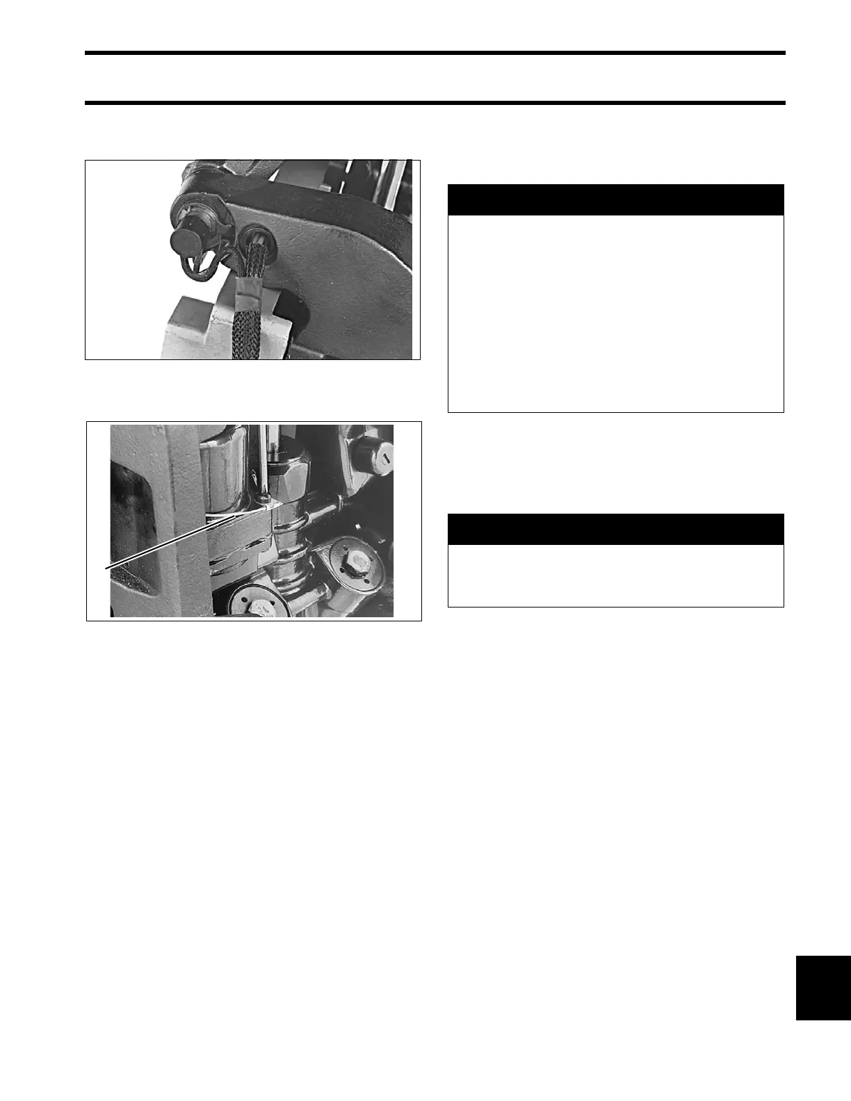
Place trim/tilt wire s in b raided tu be a nd install
through hole in the stern bracket.
Attach the ground wire to the trim/tilt unit.
Release the tilt suppor t and lower the outbo ard.
Tighten the manual release valve to a torque of 45
to 55 in. lbs. (5.1 to 6.2 N·m).
Install conne ctor on trim/ tilt cable and reconne ct
trim connectors to engine wire harness.
TRIM AND TILT SERVICE
Disassembly
Thoroughly clean the unit before disassembling it.
Scrub all o utside surfaces with a st iff brush an d
hot, soapy water to prevent surface dirt from con-
taminating internal parts.
Always use a “lint free ” shop cloth when han dling
power trim/tilt components.
If p ainting the unit is required, p aint it af ter it is
completely assembled. Painting of individual com-
ponents may ca use flakes of paint to en ter th e
hydraulic p assages dur ing assembly . Tape th e
trim/tilt piston rods before painting.
25079
1. Ground wire 25057
A WARNING
Before removing the manual release valve,
operate the unit to the full UP position,
then run the unit down mom entarily and
loosen the reservoir cap one full turn.
To avoid personal injury, always wear eye
protection wh en servic ing the hydraulic
unit. Sinc e there might be sig nificant
residual pressure be hind some compo-
nents, cover each component with a shop
cloth as you remove it.
A CAUTION
Do not apply he at to the cylinde r body or
cylinders. Excessive heat can cause high
pressure leaks or failure of parts.