9-5
WIRE / HOSE ROUTING
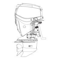
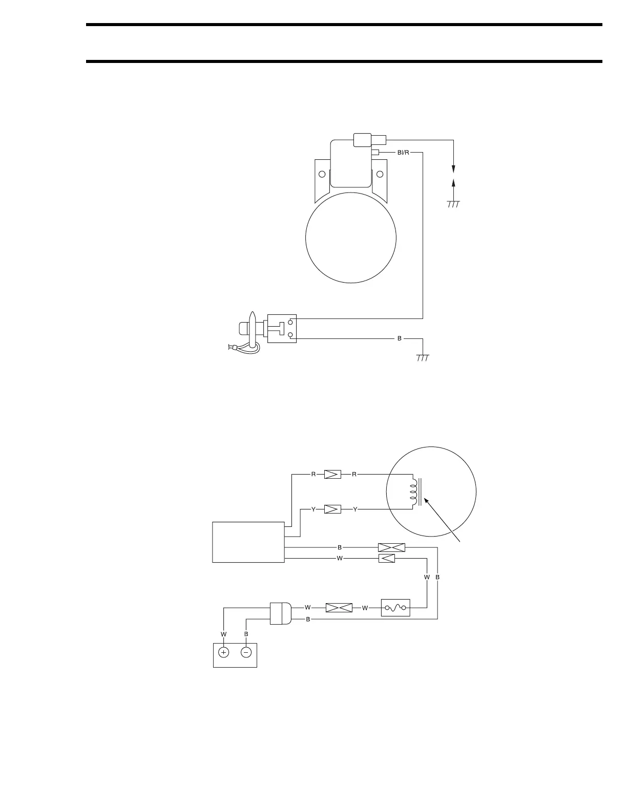
WIRING DIAGRAM
WIRING DIAGRAM
NOTE:
If installing the optional battery charge coil, the rectifier and regulator and related items, replace the orig-
inal flywheel with the optional flywheel.
CDI AND COIL UNIT
SPARK PLUG
FLYWHEEL
MAGNETO
Wire color
B: Black
B/R: Blue/Red
EMERGENCY STOP AND ENGINE STOP SWITCH
Emergency stop switch: Lock plate IN = RUN
Lock plate OUT = STOP
Emergency stop switch: Button pushed = STOP
(Optional parts)
FLYWHEEL MAGNETO
BATTERY CHARGE COIL
RECTIFIER AND
REGULATOR
BATTERY
Wire color
R: Red
Y: Yellow
B: Black
W: White
20A FUSE