9-6
WIRE / HOSE ROUTING
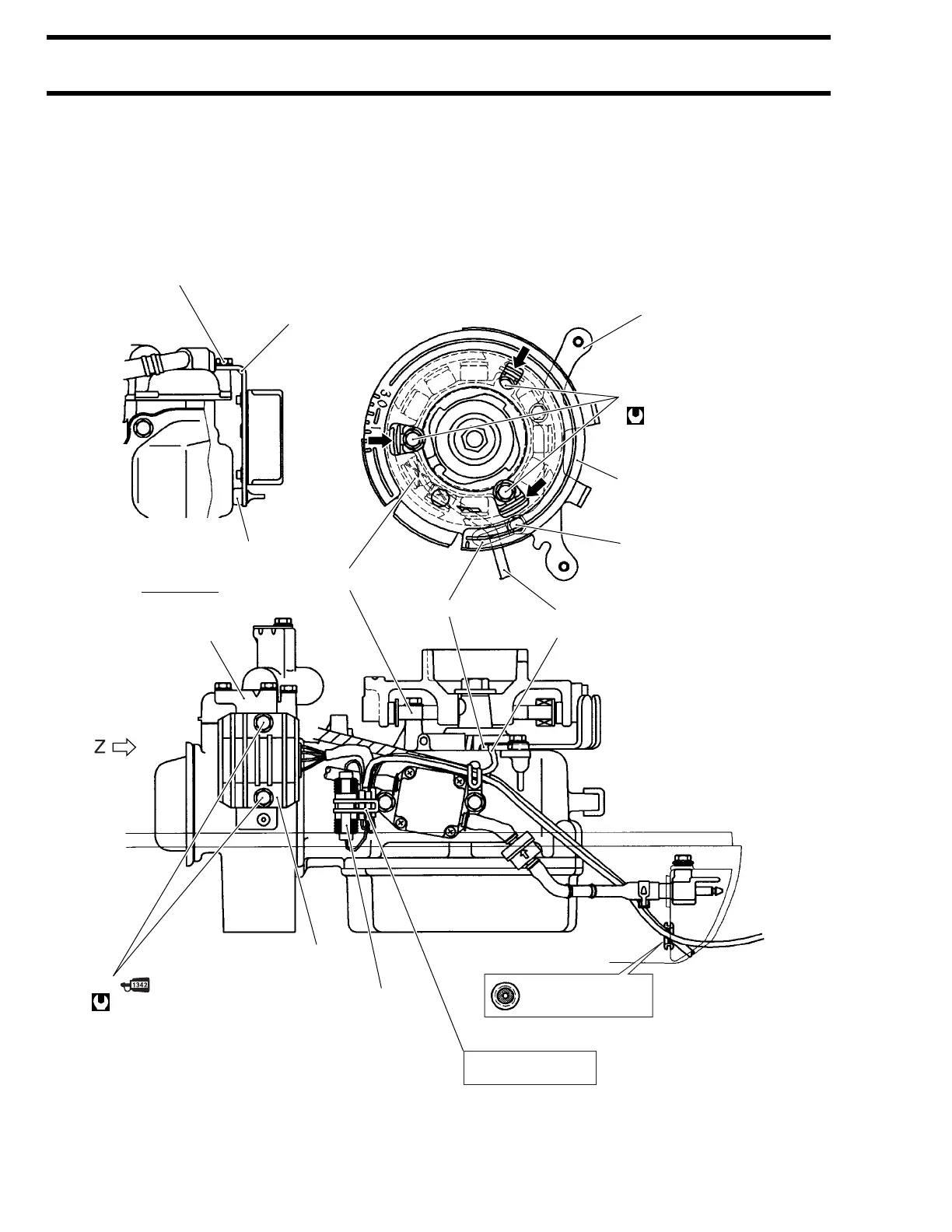
OPTIONAL ELECTRICAL PARTS INSTALLATION
OPTIONAL ELECTRICAL PARTS INSTALLATION
10 N·m (1.0 kg-m; 7.0 lb-ft)
8 N·m (0.8 kg-m; 6.0 lb-ft)
NOTE:
Before tightening the battery charge coil bolts, check that the coil is installed in
the correct position.
Visually check the clearances between the inside magnets of the flywheel and
the coil circumference by using the three holes on the flywheel.
Intake manifold
mounting bolt
Fuel tank bracket
Flywheel
Fuel tank bracket
mounting bolt
Bolt
Battery charge coil
lead wires
Clamp
Battery charge coil
VIEW Z
Bracket
Bolt
Rectifier and
regulator
Fuse case
and 20A fuse
Cut the hatched part of
the grommet.
Fix the fuse case and
the lead wires.
Clamp
Bracket
Cushion