2-11
PERIODIC MAINTENANCE
VALVE CLEARANCE
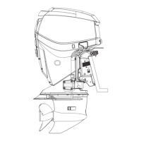
4. Measure the valve clearance by inserting thickness
gauge between the valve stem end and the rocker arm.
Thickness gauge
Valve clearance (cold engine condition):
IN 0.03 – 0.07 mm (0.001 – 0.003 in)
EX 0.03 – 0.07 mm (0.001 – 0.003 in)
If the valve clearance is out of the specification, adjust
the clearance.
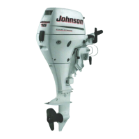
Adjustment
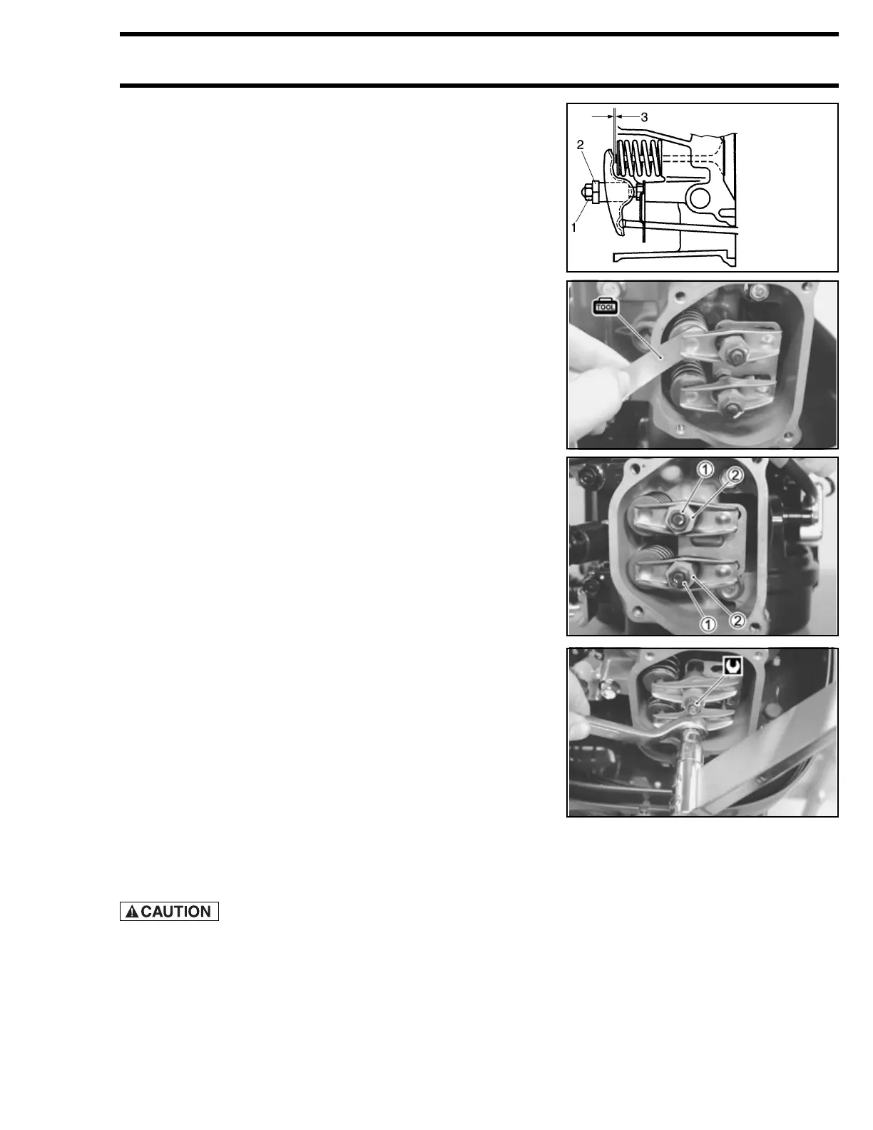
5. Loosen the valve adjusting lock nut 1 while holding the
pivot nut 2.
6. Turn the pivot nut 2 to bring the valve clearance to within
the specification.
Thickness gauge
7. Tighten the lock nut 1 to the specified torque while hold-
ing the pivot nut 2.
Valve adjusting lock nut: 11 N·m (1.1 kg-m; 8.0 lb-ft)
8. Recheck the valve clearance.
Installation
Installation is reverse order of removal with the special atten-
tion to the following steps.
• Tighten the four cylinder head cover bolts diagonally to the
specified torque.
Cylinder head cover bolt: 8 N·m (0.8 kg-m; 6.0 lb-ft)
Do not re-use the gasket once removed. Always use a
new gasket.
• Make sure that the cylinder head cover gasket is installed
correctly. (See page 6-39)
1. Lock nut
2. Pivot nut
3. Valve clearance