System Components
22 / 120 H157654_9_011
3.2 Console and Other System Components
The next table lists the various parts of the console, monitoring & control units. Please also
refer to the floor plan diagrams beginning in the chapter Floor Plan [}79]. These scaled dia-
grams provide an idea of where the various pieces of NMR equipment should be placed.
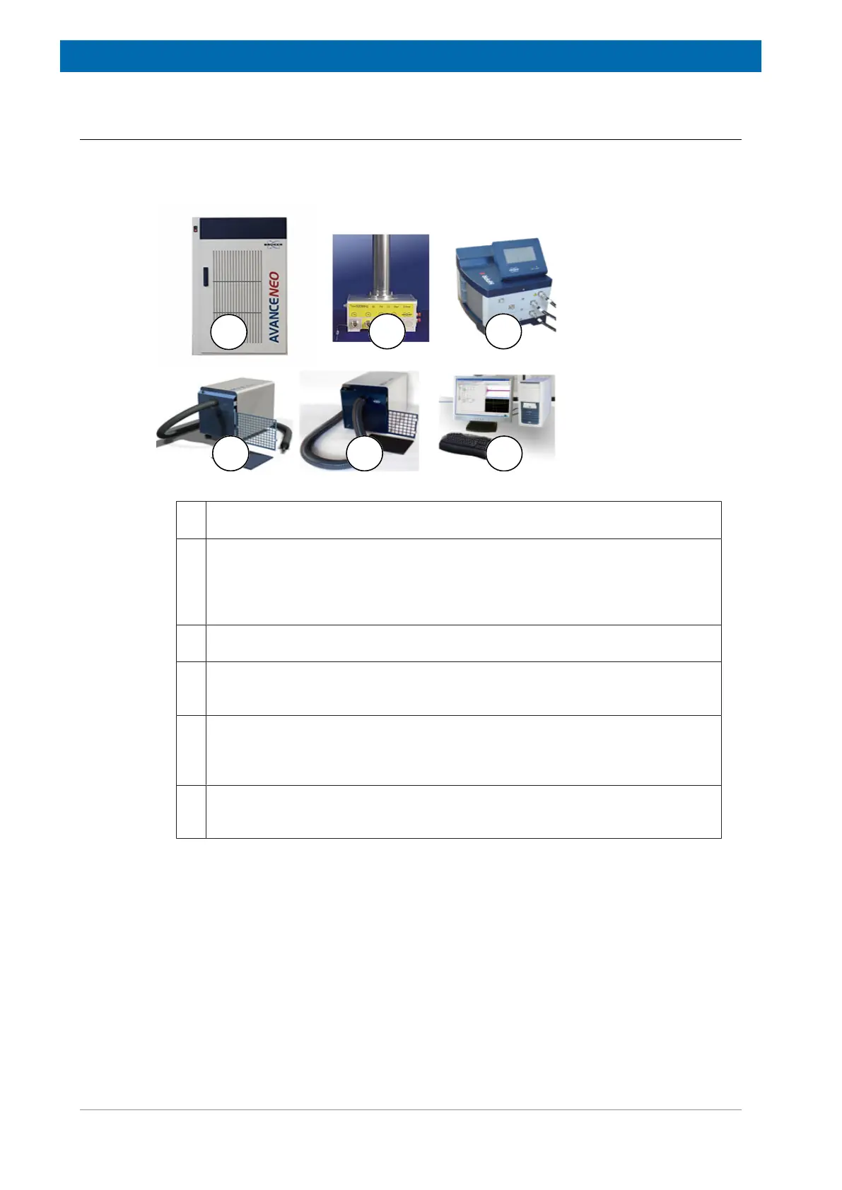
Figure3.1: Spectrometer and Magnet Control
1. The AVANCE NEO console main cabinet, where the actual NMR data acquisi-
tion is performed.
2. The probe, which is designed to hold the sample, transmit radio frequency sig-
nals which excite the sample and receive the emitted response. The probe is in-
serted into the bottom of the magnet and sits inside the room temperature shims.
Coaxial cables carry the excitation signals from the console amplifiers to the
probe and the NMR signal back from the sample to the receiver.
3. The HPPR/2 amplifies, filters and routes the NMR response signals from the
probe to the RX22 receiver. It switches the RF transmitter output to the probe.
4. The BCU-II Unit delivers very cold gas, either nitrogen or dry air, through a flexi-
ble isolated non-magnetic transfer line. It is possible to control the sample tem-
perature down to -60°C inside the probe for solid or liquid NMR applications.
5. The BCU-I Unit cools VT gas to allow proper sample temperature regulation. The
unit reduces the temperature of the air input (supplied by the variable-tempera-
ture unit) and provides cooling of the NMR sample within the magnet to at least
-5 °C for a room temperature of 25 °C.
6. The workstation acts as the operational computer for the user processing NMR
data and sending/receiving data to/from the acquisition computer in the main con-
sole.
 Loading...