Utility Requirements
H157654_9_011 67 / 120
8.3.4 Compressed Air System
When designing a suitable compressed air system, the following points must be taken into
consideration:
• To prevent magnetic impurities from entering the magnet use only copper or stainless
steel lines. Do not use iron or steel pipes. Plastic piping is unsuitable where very low dew
points are required. Water vapor in the air will permeate plastic piping limiting minimum
dew points to typically -25°C.
• To avoid surges in the air pressure (e.g. during sample lift) install a container of 10-20
liters in the air supply line to act as a buffer. Locate the buffer after the dryers in the sup-
ply line. Buffer containers must meet the appropriate safety requirements. They must
have a working pressure of 16 bar and be proofed up to 30 bar. Use tanks which are in-
ternally coated with water and acid resistant material. This will prevent corrosion from im-
purities such as SO
2
.
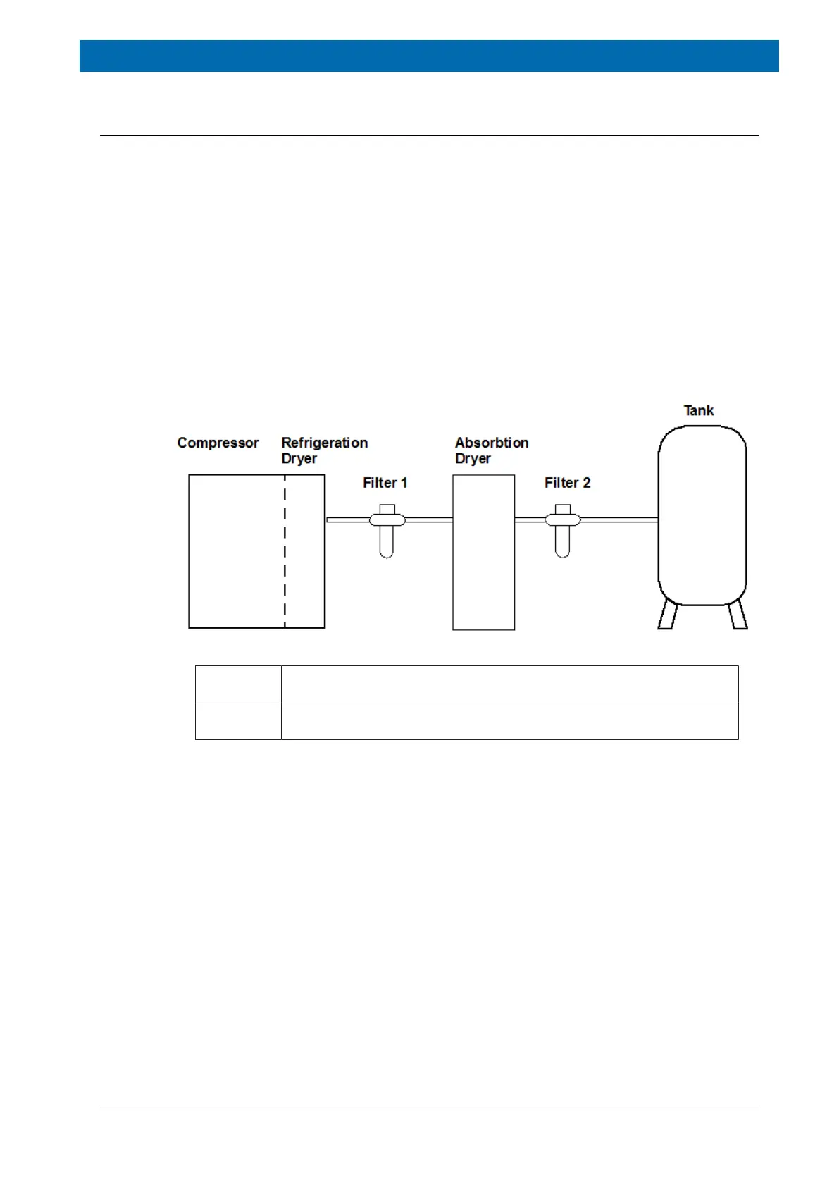
The three major components in a suitable compressed air supply line include the compres-
sor, dryer and appropriate filters:
Figure8.3: Example of a Typical Dryer/Filter System Setup
Filter 1: General purpose liquid and dust removal filter (0.1 mg/m
3
- 0.1 ppm, 1
micron).
Filter 2: High-efficiency dust, liquid and aeresol filter (0.1 mg/m
3
- 0.01 ppm, 1
micron).
When using a dryer/filter system setup, the following questions should be addressed:
• Pressure loss in piping?
• Efficiency loss in dryer?
• Pressure loss in filter?
• What is the required pressure?
• What is the required flow rate?

 Loading...