45
ZTKS0156 / Z31820 / Rev.: 03
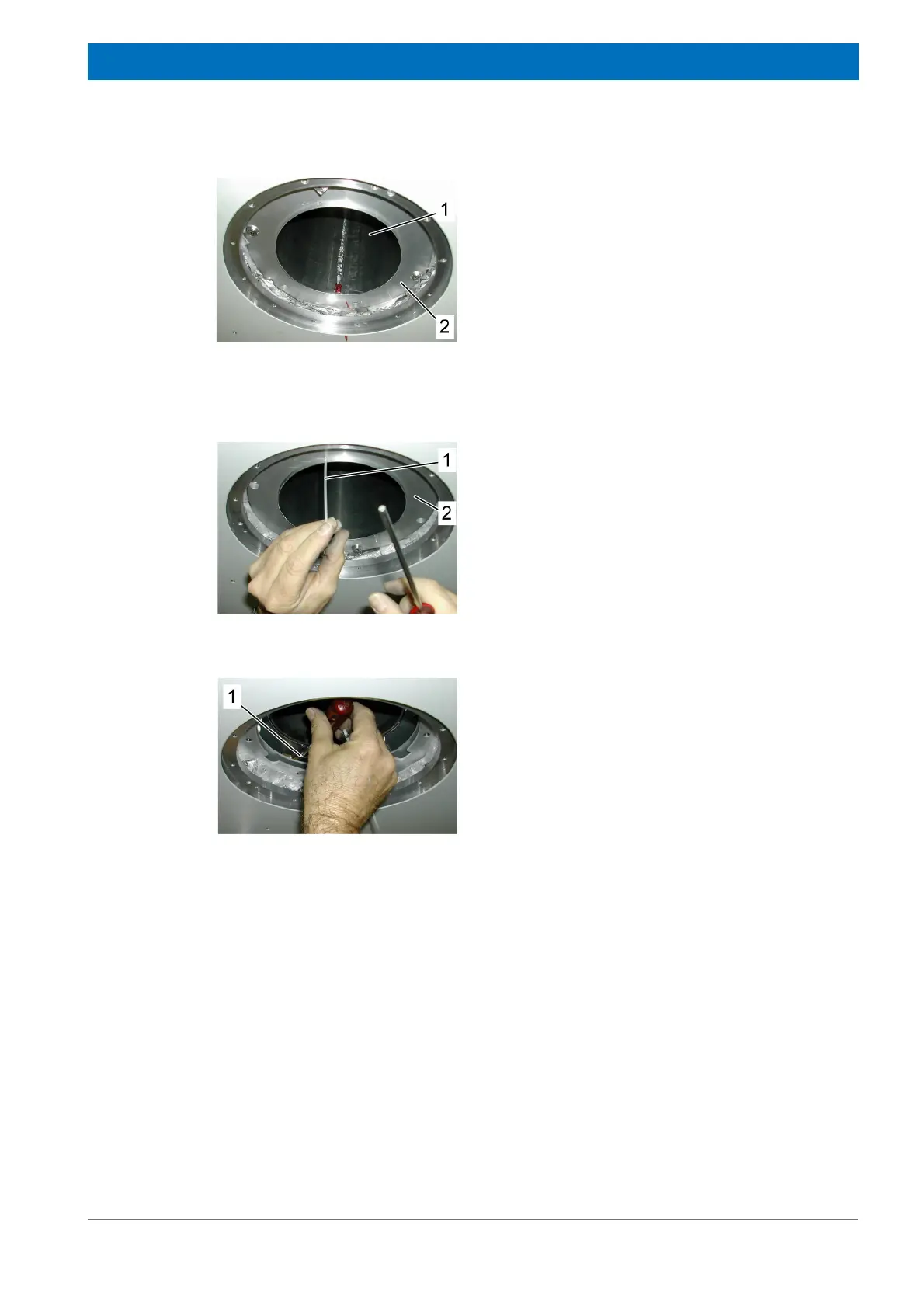
Assembling
Bottom of the Cryostat
Figure 4.14: Assembling the Nitrogen Tube - step 3
3. Insert and fix the lower nitrogen contact
flange (2). Be careful with the super insula-
tion.
4. Clean the nitrogen tube with ethanol. Pre-
vent any contamination (finger prints, dirt
e.g.) to the nitrogen tube surface by using
clean gloves. Prevent any damage (scrat-
ches, buckling) to the nitrogen tube by hand-
ling it carefully.
5. Insert the nitrogen (1) tube from the top.
Figure 4.15: Assembling the Nitrogen Tube - step 4
6. Check the distance between the nitrogen
and helium vessel by inserting the alignment
tool (1) into the three check holes of the
nitrogen contact flange (2). The insertion/
extraction of the alignment tool (1) should be
smooth.
Figure 4.16: Assembling the Nitrogen Tube - step 5
7. If the alignment tool does not insert/extract
smoothly, remove the nitrogen tube and
lower nitrogen contact flange and adjust the
alignment with the alignment rods (1)
(loosen/tighten).
8. Remount the nitrogen tube and nitrogen
contact flange and check the alignment.
9. If the alignment is correct, fix the nitrogen
contact flange.