EasyManua.ls Logo

Bruker RS - Mounting the Rotary Valve Column

Bruker RS
157 pages
Print Icon
To Next Page IconTo Next Page
To Previous Page IconTo Previous Page
Loading...
56
ZTKS0156 / Z31820 / Rev.: 03
Assembling
4.3.3.2 Mounting the Rotary Valve Column
Figure 4.37: Mounting the Cold Head - step 5
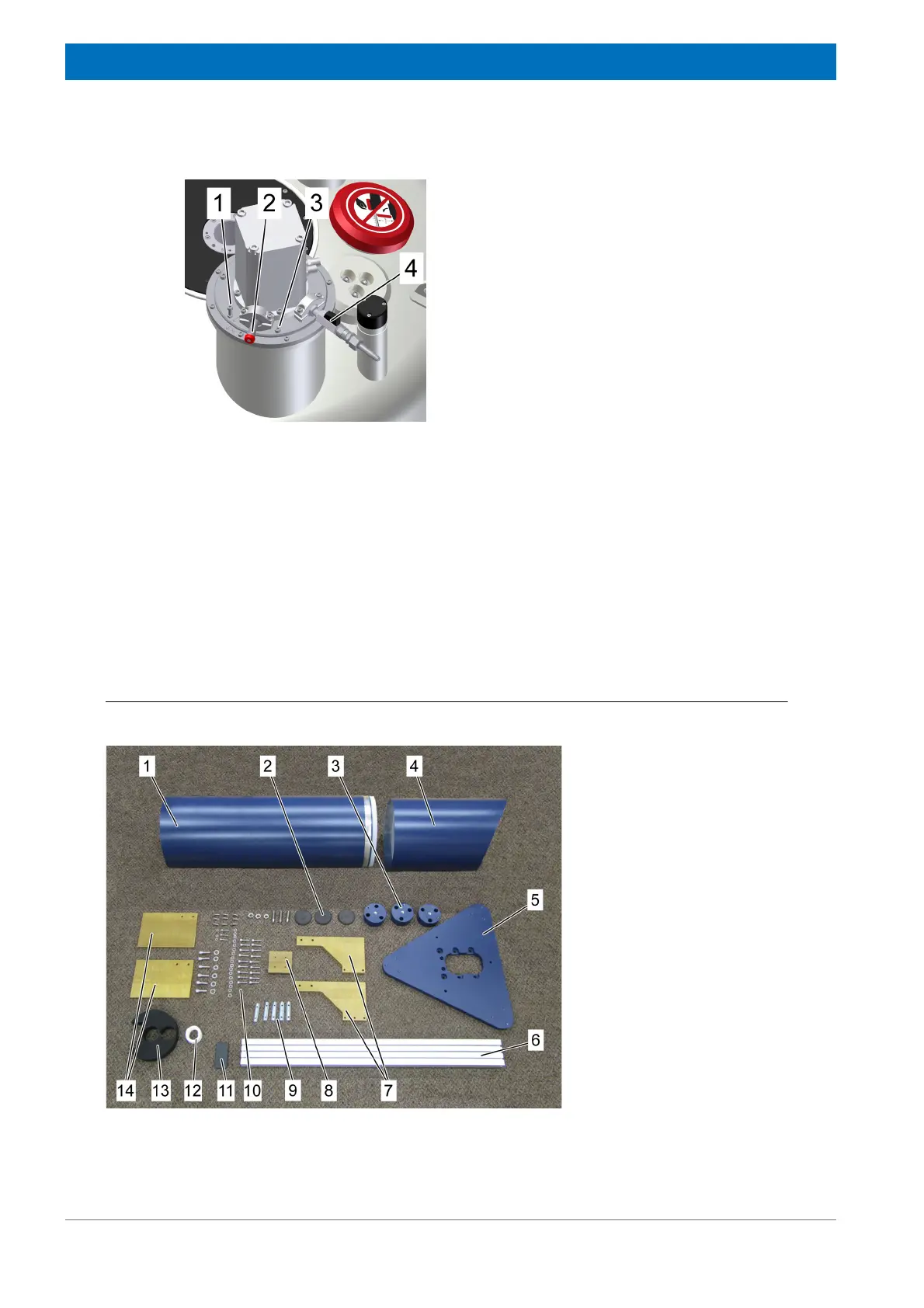
13. Set the M 5 adjustment screws (1) to the
turret flange and tighten them by one turn.
The cold head is lifted 0.8 mm.
14. Fix the adjustment screws (1) with the three
nuts on top of the cold head flange.
15. Attach the three M 6 fixing screws (3). Do
not tighten these screws yet.
16. Slightly grease the O-ring and sealing sur-
face of the KF 16 flange before assembling
the pressure relief valve (2).
17. Assemble the pressure relief valve (2) to the
KF 16 flange.
18. Slightly grease the O-ring and sealing sur-
face of the KF 16 flange before mounting
the stop valve (2).
19. Assemble the stop valve (2) to the KF 16
flange and open it.
Figure 4.38: Rotary Valve Column - overview
1 Noise protection cover
2 Stand plates (each 3x)
3 Base supports (3x)
4 Noise protection cap
5 Base plate
6 Profile rail
7 Adapter plate
8 Front plates
9 Sliding blocks
10 Accessories
11 Profile cap
12 Velcro® fastener
13 Flex line positioning disc
14 Stand plates (2x)

Table of Contents

Related product manuals