55
ZTKS0156 / Z31820 / Rev.: 03
Assembling
i
The cold head tubes are sensitive against forces in any direction. Do not remove the
cold head insulation. Handle the cold head carefully.
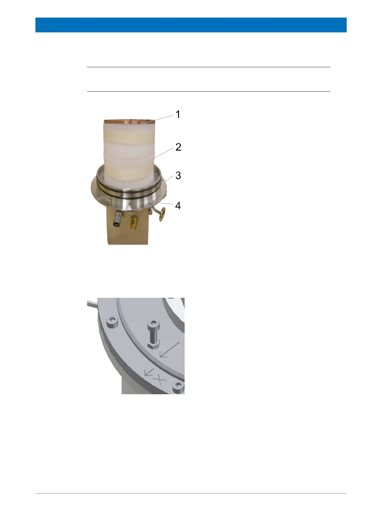
Figure 4.35: Mounting the Cold Head - step 3
5. Carefully remove the cold head from its box
and place it upside down on a clean and
stable work surface. Keep the box for future
transportation.
6. Check if the copper flange (1) is assembled
correctly and clean the surface.
7. Check if the insulation (2) is assembled cor-
rectly.
8. Clean and grease the two O-rings (3) before
mounting them on the cold head flange.
9. Assemble the three M 5 adjustment screws
(4) to the cold head flange. The thread
should not be visible at the O-ring side of the
flange.
10. Turn the cold head carefully and set it on the
copper flange.
Figure 4.36: Mounting the Cold Head - step 4
11. Mount the cold head in the cold head turret
respecting the orientation. Match the marks
“X” on the cold head flange top side and on
the cold head turret top flange.
12. Insert the cold head until rigid contact to the
bottom of the cold head turret.
The assembly is correct, if there is a gap of
about 2 mm between cold head flange and
turret flange.