46
ZTKS0156 / Z31820 / Rev.: 03
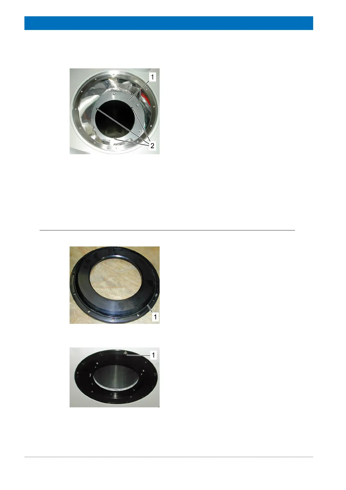
Assembling
Top of the Cryostat
4.3.1.5 Assembling the RT Tube
Bottom of the Cryostat
Figure 4.17: Assembling the Nitrogen Tube - step 6
10. Mount the upper nitrogen reduction flange
(1).
11. Adjust the distance between the nitrogen
and helium vessel by inserting the alignment
tool into the three check holes of the nitro-
gen contact flange (2).
12. Fix the upper nitrogen contact flange (1).
13. Check the alignment tool (2) for free
movement. Remove the alignment tool.
14. Close the cuts of the super insulation with
polyester tape without taping the insulation
to other surfaces.
Figure 4.18: Assembling the RT Tube - step 1
1. Check the O-ring slot (1) of the lower RT
reduction flange.
2. Remove scratches, if necessary.
3. Clean the O-ring slot with ethanol.
4. Clean the O-ring with ethanol.
5. Grease the O-ring with vacuum grease and
place it into the O-ring slot. Prevent
contamination with dust and dirt.
Figure 4.19: Assembling the RT Tube - step 2
6. Grease the twelve M 5 x 12 screws (1) with
screw grease.
7. Insert the lower RT reduction flange from
the bottom. Check the index. The lower RT
reduction flange can be inserted in only one
position.
8. Fix the lower RT reduction flange with the
twelve screws (torque 12 Nm).