57
ZTKS0156 / Z31820 / Rev.: 03
Assembling
i
The spikes of the base plate should be protected with the supplied plastic cap nuts until
the rotary valve column is in its final position to prevent damage to the floor surface.
These plastic cap nuts have to be removed before operating the magnet system.
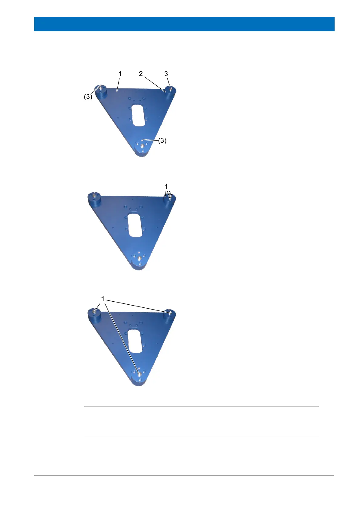
Figure 4.39: Mounting the Rotary Valve Column - step 1
1. Put the base plate (1) upside down.
2. Arrange the three base supports (2) as
shown in the figure with the tapered bores
(3) on topside.
Figure 4.40: Mounting the Rotary Valve Column - step 2
3. Mount the three base supports to the base
plate with three M 8 x 25 screws (1) per sup-
port.
4. Tighten the screws (torque 20 Nm).
Figure 4.41: Mounting the Rotary Valve Column - step 3
5. Attach the spikes (1) into the middle thread
of the three base supports.