BTL-5000 SERIES
USER'S MANUAL
page 45 of 56
Output voltage - HVT max. 390 V (maximum instantaneous value)
*maximum value for some currents is limited according to IEC 601-2-10
Tolerance of output amplitude
± 10 % for 5 mA (5 V, 5 µA) and higher; otherwise ± 30 %
± 10 % for 35 V and higher; otherwise ± 30 % (for HVT)
Tolerance of time parameters of current
standard ± 5 %; maximum ± 15 %
standard ± 20 % for modulation of HVT from 5 s; otherwise ± 30 %
Nominal load impedance
500 Ω
Internal output resistance in CV mode
96 Ω ± 10 %
Internal output resistance in CC mode
47 kΩ ± 10 %
Output capacity standard 150 pF
Output polarity – can be selected positive / negative / with reversal in the middle of the therapy
Positive polarity red banana plug = + = anode; black banana plug = - = cathode
Negative polarity red banana plug = - = cathode; black banana plug = + = anode
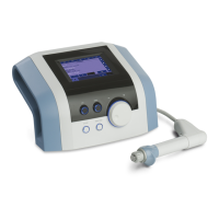
7.2 BASIC PARAMETERS OF ULTRASOUND GENERATOR
Adjustable values
Effective intensity
Continuous operation
0.1 to 2 W/cm
2
± 20 % for output intensity higher than 0.2W/cm
2
Pulse operation
0.1 to 3 W/cm
2
± 20 % for output intensity higher than 0.2W/cm
2
Working frequency
1 MHz ± 5 % and 3.2 MHz ± 5 %
Modulation frequency
10 to 150 Hz ± 5 %
Duty factor
6 to 100 % ± 5 % of the set value
Duty factor – default
6.25 % (1:16); 12.5 % (1:8); 25 % (1:4); 50 % (1:2), 100% (1:1) ± 5 %
of the set value
Maximum output power 12W
Parameters of pulses
Duty
factor
Frequency 10 Hz
period 100 ms
Frequency 50 Hz
period 20 ms
Frequency 100Hz
period 10 ms
Frequency 150 Hz
period 6.67 ms
Pulse
length
Pause
length
Pulse
length
Pause
length
Pulse
length
Pause
length
Pulse
length
Pause
length
50 %
50 ms 50 ms 10 ms 10 ms 5 ms 5 ms 3.33 ms 3.33 ms
25%
25 ms 75 ms 5 ms 15 ms 2.5 ms 7.5 ms 1.67 ms 5 ms
10%
10 ms 90 ms 2 ms 18 ms 1 ms 9 ms 0.67 ms 6 ms
6%
6 ms 94 ms 1.2 ms 18.8 ms 0.6 ms 9.4 ms 0.40 ms 6.27 ms
Steps of adjustable values
Intensity 0.1 W/cm
2
Modulation frequency 10 Hz
Duty factor 1%
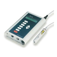
7.3 BASIC PARAMETERS OF LASER GENERATOR
Indication of emission of laser radiation green pilot light on the probe, supplementary lighting of the
probe/cluster, sound
Indication of readiness for emission on the screen
Indication of unreadiness for emission on the screen
Additional safety means - warning labels on the device case and on the probe/cluster
- warning label for the entrance door of the workplace
- connector of the remote control
Connector of the remote control (door switch)
input voltage AC / DC 5 V to 35 V (external power supply) / automatic polarity
recognition
input current max. 10mA
active level settable positive / negative logic