5
1502154 Rev D Configuration 5-7
➤ To perform temperature compensation
1. For both forward balancing carriers, note the loss (in dB at the carrier frequency) due to the
cable preceding the unit under test. Note the temperature of the air surrounding the
preceding cable.
2. Using Figure 5.3 on page 5-8, obtain a Temperature Compensation Value (TCV) for that
section of cable for each carrier.
a. Find the intersecting point on the chart corresponding to your cable loss and
temperature values.
b. Find the TCV line nearest this point. The dB value label on that line is your TCV.
c. Record both TCVs in the calculation box below and on the Flex Max901e Data Sheet.
Example: Your cable loss is 23dB. The air temperature is 25°F (–5°C). The point on
the graph corresponding to these two values is between the 0.75 and 1.0dB lines,
but closer to the 1.0dB line. (The dotted lines mark the halfway-between-lines
points on the graph.) The TCV is then 1.0dB.
3. Record the System Forward High and Low Balancing Carrier levels from the Flex Max901e
Data Sheet into the following calculation box. Perform the calculation to get the adjusted
output levels.
4. Use the temperature compensated forward balancing carrier levels in Factory-Shipped
Configurations for Flex Max901e Trunk and Bridger Amplifiers on page 5-9 and Forward Field
Testing on page 6-4.
5. If necessary, repeat Steps 1 and 2 for the return balancing carriers. Use these temperature
compensated levels in Return Balancing on page 5-20 and Return Field Testing on page 6-5.
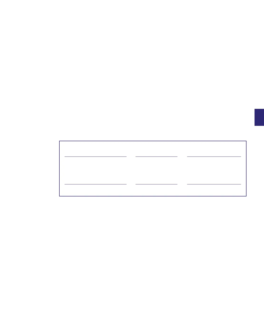
+ =
System Forward High Balancing
Carrier Level
TCV For High Carrier
(from Figure 5.3)
Adjusted Forward High
Balancing Carrier Level
+ =
System Forward Low Balancing
Carrier Level
TCV For Low Carrier
(from Figure 5.3)
Adjusted Forward Low
Balancing Carrier Level