5
1502154 Rev D Configuration 5-23
➤ To balance the return path
1. Obtain the Return High and Low Balancing Carrier Levels from the System Map for both
amplifiers. Record these levels in the corresponding boxes on the Amplifier Data Sheet and
as shown in the following boxes in Steps 3c and 4a. (Return input levels may vary
depending upon the input port.)
2. Set the Flex Max901e as follows:
a. At the Balancing Amplifier, ensure that NPB-000/SEQ-0 accessories are installed in
the STATION REV PAD and STATION REV EQ locations.
b. If the system calls for one, install an NPB series PAD in the STATION REV PAD
location in the Balancing Amplifier.
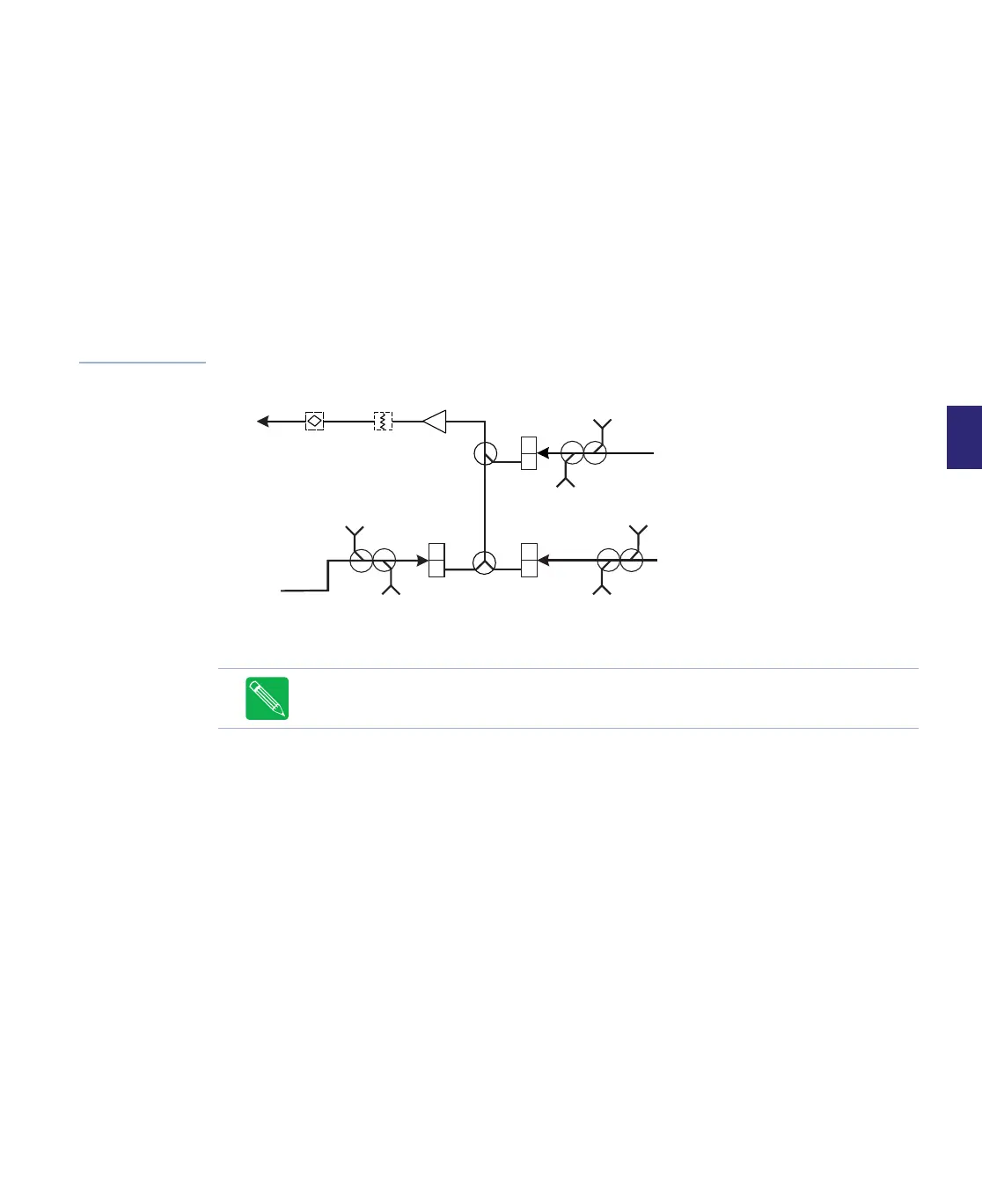
Figure 5.12
Simplified Return
Path Block Diagram
3. Equalize the RF signal:
a. At the Balancing Amplifier:
■ For Trunk amplifiers, connect a signal generator to the PORT 4 OUTPUT TP.
■ For Bridgers amplifiers, a signal generator to the P2/P3 OUTPUT TP.
b. Set the Signal Generator to output the system Return High and Low Balancing
carriers (plus 20 or 25dB to compensate for the RF module testpoint loss; see the
module label for testpoint loss).
c. At the Measuring Amplifier, connect a signal level meter to the return input testpoint
of the associated port. Measure the Return High and Low Balancing Carrier Levels
and record them as shown in the following calculation box.
Note Do not terminate the unused port testpoint as it can affect testpoint accuracy.
H
L
H
L
H
L
Port 4
Ports
2 and 3
Ports
5 and 6
Port 1
REV
EQ
STATION
REV PAD
PORT 4
REV I/P
TP
PORT 4
FWD O/P
TP
PORT 2/3
REV
I/P TP
PORT 2/3
FWD
O/P TP
PORT 5/6
REV I/P
TP
PORT 5/6
FWD O/P
TP